neazoi
Advanced Member level 6
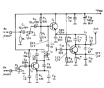
Hello I have found this audio video modulator.
https://www.qsl.net/va3iul/Homebrew_RF_Circuit_Design_Ideas/A-V_Transmitter_ZP5ZDM.gif
The author states that it works ok without using an audio transformer.
Can it be done or is it hoax?
https://www.qsl.net/va3iul/Homebrew_RF_Circuit_Design_Ideas/A-V_Transmitter_ZP5ZDM.gif
The author states that it works ok without using an audio transformer.
Can it be done or is it hoax?