Continue to Site

Welcome to EDAboard.com

Welcome to our site! EDAboard.com is an international Electronics Discussion Forum focused on EDA software, circuits, schematics, books, theory, papers, asic, pld, 8051, DSP, Network, RF, Analog Design, PCB, Service Manuals... and a whole lot more! To participate you need to register. Registration is free. Click here to register now.

Simple oscillator or frequency doubler??

Status
Not open for further replies.

Eliphas Levi

Newbie level 4
Joined
Mar 10, 2013
Messages
6
Helped
0
Reputation
0
Reaction score
0
Trophy points
1,281
Location
EA
Activity points
1,388
oscillator.JPG

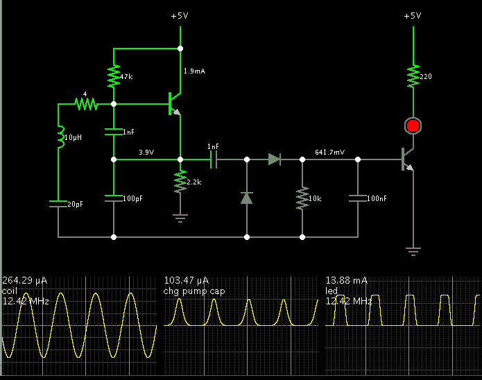
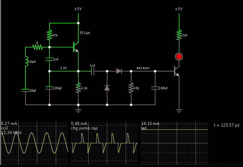
Well, hello to one and all. This being my first post I face a dilemma whether to add more pleasantries or get right down to business, I choose the latter and please correct me if I have been found wanting. The above circuit is an oscillator which I picked up on the internet and used. All seemed well till I realized that the frequency which I see on the oscilloscope is a little more than double the frequency of the resonator used. So I thought that the problem must with the resonator and that the resonator must perhaps (against all odds) be marked by the manufacturer as half the frequency of which it actually is. So I changed the resonator(crystal) but still this phenomenon perseveres. So I came to the conclusion that there is something amiss in my understanding of this circuit and any comments which you may provide will be helpful.

PS : I did not have the 1N914 diodes so I used 1N4007 simply because I had no other diode knowing full well that 4007 is a rectifier diode and 914 is a small signal diode. I did not expect results but fortunately I got the wave. Later on I replaced the 4007 with 4148 and surprisingly I did not get any wave. If anyone would care to comment on that too, it would be simply delightful.
 

This looks to be a crystal tester rather than an oscillator. I think the intention is that any crystal capable of causing oscillation produces a signal which is passed to the voltage doubling rectifier and in turn makes the transistor conduct and the LED light up.

It will never work properly with 1N4007 diodes, their reaction time is far too slow to work with crystals of more than maybe a hundred KHz or so but their effective high capacitance may allow the first transistor to oscillate when otherwise it would not. Incidentally, there is a connection 'dot' missing from the schematic, there should be one at the top of R2.

Brian.
 
Crystal-Resonator.gif

@ chuckey - This is how the resonator looks, I do understand that you asked for specs but the thing is, I got it from an electronics shop here and the guy selling those is never really in the "I am your friend" mode, so here we just buy a part and make do any way we can. From what is written on the crystal I know that the manufacturer is KDS and that the frequency is 12 MHz. KDS I found is a Japanese company, so I went to the site to do a quick search but I came up with nothing unfortunately. Following your advice I changed C1, but the only difference it made was reduce the V (p-p) from 200 mV to around 80 mV.

@ betwixt :- you are absolutely right about the supposed operation of the circuit, but the LED does not light up as the voltage which is passing through to the LED is in the mV range and I was unable to understand why the frequency was doubled, when you mentioned the voltage doubling rectifier I did a quick search and found that the circuit is Greinacher voltage doubling rectifier circuit. Thanks for that. 1N4007 should not allow the circuit to work properly but somehow it is and that has left me befuddled (I think that's the word ;-)). But after your reply I replaced the 4007 with 4148 just to see how it goes (in fact I removed everything and made it again), this time I got a signal but the V (p-p) is reduced, apart from that I observed no difference on the oscilloscope. I have an oscilloscope which is supposed to show waveforms of upto 30 MHz, but even at 24 MHz you have to strain your eyes to observe anything, perhaps that is why I am unable to see any difference in the wave, ripples or anything else of significance apart from the voltage levels.
Again, you are right a connection dot is missing, my bad.

On a side note, can anyone tell me why is it that after every few minutes I am being logged out and have to sign in. Can I not stay signed in till I choose to sign out?
 

Where are you measuring the signal? Anything beyond D1 should only have DC on it so if you are measuring from the second transistor there should not be any visible waveform. If you want to check using an oscilloscope, the best place is across R2. You should be aware that the values in the schematic are probably not the best to use. It isn't a design fault, just that each frequency has optimal values but it is designed to work over a wide frequency range of crystal so compromises have been made.

If you are measuring anywhere after D1, the 1N4007 probably seems to have worked because it was inefficient at being a rectifier at your crystal frequency. Small signal diodes like the 1N4148 would be better at converting the AC from the oscillator to DC to drive the LED so they would 'remove' more of the waveform.

I'm not sure why you are being logged out - perhaps one of the moderators can help you. I think you do need to have cookies allowed for proper operation, perhaps that's the problem.

Befuddled = confused and puzzled = how I spend most of my life :grin:

Brian.
 

I've been playing with a simulation. There is a mode where it oscillates, for a while.

Since this simulator does not include a crystal, I used a series LC, adjusted to resonate around 12 MHz. I don't claim this is an accurate model for a crystal, but it does start oscillating on its own.


I have a suspicion that whoever drew the original schematic reversed R2 by connecting it at one end and disconnecting it at the other.
I used betwixt's recommendation to connect its upper end to the node.
I also detached its lower end from the other components. Now it is zero ground.

There is now a couple mA flowing through the transistor. Now the rest of the circuit has a little more juice to power it.

I reduced the resistor above the LED, to make it brighter.

- - - Updated - - -

I remember after I first signed on this board, I would be taking a long time to edit a post, then find I was logged out. I had to re-enter my name and password.

To avoid losing my work, I got in the habit of highlighting and copying it, before posting.

Eventually I must have built up sufficient activity, because now I seem to be logged in all the time. I don't remember the last time I had to enter my name and password.
 

I'm not saying it's a good circuit in the first place - it isn't, but to work as the designed intended the ground side was correct in the first schematic. The two diodes, C3 and C4 are a standard voltage doubler, fed from the oscillator and feeding the resulting DC directly into the base of the second transistor. As such, the rectifier and the transistor emitter must share the same ground.

It's performance could be improved by adding a capacitor across the supply and by adding an inductance in series with R2 to increase the impedance at that point. I would also make C1 and C2 the same value but exactly what that should be depends on the crystal being tested. A 'ball park' figure I would suggest is 220pF for say 100KHz to 50MHz crystals. For higher frequencies it may be necessary to add a small capacitor (47pF?) in series withthe crystal to stop it being pulled too far off frequency. A transistor intended for RF use might also work better.

Brian.
 

Yes, I re-connected the other components to ground, in addition to the resistor.


Now the circuit operates consistently (in simulation that is)... after I let it go for 1200 cycles. It takes that long for the volt level to rise high enough and turn on the transistor bias. It's only 1/10 of a milli-Sec, but I guess I had to learn to be patient.
 
On a side note, can anyone tell me why is it that after every few minutes I am being logged out and have to sign in. Can I not stay signed in till I choose to sign out?
When you log in, tick the "remember me" box. Then you will stay logged in forever, or until you choose to log out.


Wow! Those were invaluable inputs, I think I understand the circuit a lot better now. I am actually working at making a simple wireless communication module and this was the first step, to produce the carrier frequency using a resonator or a tank circuit. If I wanted to use the oscillations produced by the resonator would you recommend that I remove everything from C2 onwards and then give that waveform as the carrier to the modulator or would I be committing a grave and ignorant act? Let me explain what I actually hope to achieve. I would be using a carrier (hopefully this one) and frequency modulating it with a 50% duty cycle square wave from a 555 timer working as an astable multivibrator and then finally power amplifying the signal and radiating it. Then I would receive it with a tuned circuit and again amplify and feed the signal into a 555 timer which would be working as a Schmitt Trigger, this would then constitute the demodulating of the signal. After this Morse code transmission I would also be trying to transmit audio signals.

@ betwixt - I was measuring the signal across R2 and also across the LED. Across the resistor I was getting a sine wave of double the frequency of the oscillator (which is fine by me, I don't want to change the frequency, just want to understand why it is being doubled) and across the LED I am getting a wave of the same frequency but it is slightly triangular in appearance. As for the suggestions you provided about changing the values I will incorporate them and let you know what happens. Again thank you. I will be taking the liberty of troubling you more often than not with more and more questions.

@ BradtheRad - Thank you for taking out the time to actually run the simulation, I am grateful. Would you be kind enough to tell me which software you are using. I have access to Proteus, Multisim, AWR and also Agilent's ADS. I tried this with Proteus and Multisim but both have been unable to provide me with a successful simulation at any signal which runs over a few hundred kilohertz and AWR and ADS are more appropriate for microwave designing. I am using Windows 7 but also have Linux (Fedora) if any software you suggest requires it. Gratitude.

- - - Updated - - -

@ godfreyl - Thanks. I will now remember to ask the site to remember me. :lol:

- - - Updated - - -

Oh and I almost forgot, I am following the steps on this link.
http://www.pyroelectro.com/projects/pyro_rf_transmitter_27mhz/index.html
Though the carrier part on this link did not seem to give me any results at generating the carrier frequency hence my wandering about the internet in hope of finding an oscillator circuit which would work for me.
 

You have a fundamental flaw in the design if you want to use it for FM - it will only allow a tiny amount of frequency deviation because of the high 'Q' of the crystal. There will be some deviation but possibly not enough for what you are trying to do. There is nothing in the oscillator that would double the frequency but being very generic, it's possible it is making a crystal work in overtone mode.

The better solution is to use an LC tuned circuit and apply the modulation by means of varying the tuning capacitance with a varactor diode. It depends on how much frequency stability you need and what the actual frequency is. The 'professional grade' solution would be to use an LC oscillator and provide two tuning controls, one to apply the modulation and one for maintaing it on frequency. A PLL would compare the average frequency with a reference frequency and adjust the tuning if necessary to compensate for drift. With todays PLL devices it's actually quite easy to build stable but adjustable oscillators.

Brian.
 
  • Like
Reactions: Eliphas Levi

    V

    Points: 2
    Helpful Answer Positive Rating

    Eliphas Levi

    Points: 2
    Helpful Answer Positive Rating
I had a look on the KDS website and downloaded a .PDF for HF crystals that looked like yours (H6U). Their rated load capacitances were quoted at 8,10,12 pF. **broken link removed**
Frank
 
  • Like
Reactions: Eliphas Levi

    V

    Points: 2
    Helpful Answer Positive Rating

    Eliphas Levi

    Points: 2
    Helpful Answer Positive Rating
@ BradtheRad - Thank you for taking out the time to actually run the simulation, I am grateful. Would you be kind enough to tell me which software you are using.

It is Falstad's interactive animated simulator. The entire package is a free download.

The following link will go to the website (falstad.com/circuit), load my schematic above, and run it on your computer.

https://tinyurl.com/cpsyolo

You can save the schematic by selecting Export (in the File menu), copying the text, and pasting it into a word processor, and saving it to disk. To load from disk, you must open it in the word processor, copy it, then paste into Falstad's Import window.

You can alter values by right-clicking a component, and select Edit.

Somewhere you will find a model for a crystal, which is more complex than my plain series-LC.
 
  • Like
Reactions: Eliphas Levi

    V

    Points: 2
    Helpful Answer Positive Rating

    Eliphas Levi

    Points: 2
    Helpful Answer Positive Rating
@ E-design :- That thread was very good, it answered many questions I was struggling with and also many which I did not yet have.

@ betwixt :- I will be following your advice and using a tank circuit with a varicap and a PLL for stability. Although I did not yet understand the part about overtone, why would a generic circuit cause the crystal to work in overtone mode?

@ chuckey :- Thanks a lot. :grin:

@ BradtheRad :- This software reminds me of Gandalf's dragon rocket in LOTR; small package, big results, and a lot of colors. Although I think this might require a little getting used to but looks like worth the effort. Thank you for that.

@ all :- I will be using the Falstad simulator and I will get back with results and hopefully more questions. Furthermore, I was wondering if I was going to simulate a receiver then do I replace the antenna part with a signal generator or is there some software which would simulate an RF receiver, since generating a signal which is FM modulated might be a difficult task. Should I rather just make the transmitter and receiver as a single circuit and while doing it on the breadboard, simply make the circuit discontinuous and add antennas in between?
 

Crystals are normally connected so they have the least amount of signal "drive" as possible for the function they serve. They are essentially mechanical devices, it is real movement in the slab of quartz that determines their frequency, the slab of quartz flexes back and forth at it's resonant frequency. In an ideal oscillator you provide just enough energy for it to gently oscillate and in that ocndition it is most relaible and gives the cleanest output. If you over drive the crystal it will still try to flex at resonance but other vibrations and hence frequencies may start to appear and in extreme cases the quartz shatters.

Your very generic design, is designed to work over a very wide range of crystals, basically to see if they oscillate at all rather than produce a specific clean output and as such has to cater for the worst case scenario of 'lazy' low frequency crystals which tend to need more drive power than smaller high frequency ones. With some crystals, the drive level may be sufficient that the quartz flexes twice along it's structure, giving two waves where there should be one and hence twice the frequency. It's also possible that the circuit is trying to oscillate without the crystal at all because of inductances and stray capacitance in the construction and the crystal is running at the correct frequency but only managing to 'kick' the oscillation on alternate cycles.

In simulations, the normal signal source would be a virtual signal generator connected to the antenna input. In real life, even without an antenna it's quite difficult to stop a receiver picking up a nearby transmitter. Those of us who have endured EMC testing will know what I mean. :-(


Brian.
 
So lets say I generate a carrier signal with very little signal "drive" and a message signal with a high signal "drive" would it effect the modulation process if I try to modulate signals with mismatched signal "drives"? Or do I have to increase the drive of the carrier signal before giving it to the modulator? I am understanding "drive" as the power of the signal, by an analogy I am assuming a small drive to be a form of touch and greater drive in terms of a punch. ;-).
 

Your analogy is a good one.

Before going further you have to make some decisions on the frequency you intend to use and how stable the frequency has to be. A crystal gives excellent frequecy stability, in fact so stable that it's difficult to frequency modulate them. Remember that for FM you have to shift the carrier in time with the modulation and a crystal will do it's best to stop the frequency being moved. In general, the higher the frequency the more a crystal will allow you to 'pull' it away from it's natural resonance so the greater depth of modulation you can achieve.

On the other hand, an LC oscillator is easy to frequency modulate because the 'C' can be electrically altered with a varactor (varicap) diode. Their problem is that both L and C are temperature and vibration sensitive so they tend to drift unless you take great care with the design. These adverse effects tend to be more prevalent as the frequency increases and outside influences have proportionately more control of the resonance than the fixed components.

The usual compromise it to use a mix of both methods but the circuitry gets a bit more complicated. You use an LC oscillator to set the carrier frequency and you tune it with a composite of a varactor diode and a fixed capacitor. If you vary the voltage across the diode, it's capacitance changes and so the frequency moves. You get the voltage from two sources, one is the modulation signal and the other is an "error voltage" that corrects the tuning if it drifts. The error voltage comes from comparing the LC oscillator frequency with something more stable, often a quartz crystal but by using a PLL and divider circuit, the crystal does not have to be at the same frequency (although it can be). For example, if you wanted the oscillator to be at 100MHz, you could still lock it's frequency with a crystal at say 4MHz where they are cheaper and easier to obtain. The error voltage will try to cancel the modulation voltage but by slowing down it's rate of change it's possible to keep the long term average frequency stable while still allowing instantaneous changes to carry the modulation.

Let us know your intended frequency, how much FM deviation you need and what the modulating signal is, we can then advise on the best approach.

Brian.
 
First of all, sorry for the delay.

Secondly, in reply to your question, I was thinking of using a frequency of around 34 MHz, restricted by availability of components (0.22 uH and 100 pF in series).
The deviation I think would be 10 kHz and the modulating signal for now will be a square wave from a 555 timer working in astable mode and later on I was planning to upgrade it to an audio transmission (or should I directly go for audio? that is the aim.)

I was reading about FM here **broken link removed**
and I suppose I would want to use a buffer amplifier before the final amplifier stage and of course I would want a filter before giving it to the antenna. The range I was hoping for was at least 10 mts. Here the antenna is just a wire(which is not even 1/4th the wavelength i.e. on the link that I am following), would it require any impedance matching, since I do not have the necessary equipment to measure actual impedance and would have to suffice with circuit analysis, measuring the impedance of a piece of wire used as an antenna is proving to be a difficult task.
On a side note, it was interesting to note that the crystal can still effect the frequency in later stages after it has produced it.
 

Status
Not open for further replies.

Part and Inventory Search

Welcome to EDABoard.com

Sponsor

Back
Top