Continue to Site

Welcome to EDAboard.com

Welcome to our site! EDAboard.com is an international Electronics Discussion Forum focused on EDA software, circuits, schematics, books, theory, papers, asic, pld, 8051, DSP, Network, RF, Analog Design, PCB, Service Manuals... and a whole lot more! To participate you need to register. Registration is free. Click here to register now.

Please help me solve this oscillating bandgap, thanks!

Status
Not open for further replies.

ivyahoney

Newbie level 6
Joined
Jun 8, 2012
Messages
14
Helped
0
Reputation
0
Reaction score
0
Trophy points
1,281
Activity points
1,454
sch.pngoutput.pngsch.pngoutput.png

Hi,

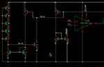
I am realizing a low voltage bandgap(shown as "sch.png"). I use a schmitt trigger to turn off the bandgap's start up circuit. The upper threshold voltage of the schmitt trigger is 500mv, and the lower threshold voltage is about 400mv. The output voltage of the bandgap circuit is designed as 760mV with its supply voltage is 1.2V.

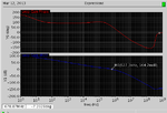
As you can see from the attached "output.png" result, the circuit is oscillating. It seems that something is repeating pulling vbg down... I don't know what is wrong with my circuit.

"vbn_su" is the gate voltage of the pull-down NMOS transistor (pull gates of PMOS current mirror down when start up).

Please help me with this, thanks a lot!
 

I would suspect that the Schmitt threshold is too close,
but on the wrong side of, the bandgap output voltage
and yet the startup circuit cannot be removed without
the bandgap core collapsing. The startup looks too simple
to me.

Start with breaking that feedback loop and see where
the startup can be removed (or, if). You may be running
off the startup alone and not even seeing the op amp
wake up, or something.
 

I have checked the threshold voltage, and there seems no problem...

I have changed another startup circuit. Please help me with this startup, will it be enough for this bandgap structure?

1 My amplifier is a two-stage amplifier with miller compensation, when I plot the loop gain and phase, there exists a zero in GBW. Will it be the reason that my bandgap does not work stable?

2 When I use ideal opamp instead of two-stage amplifier with miller compensation, the bandgap circuit works well.

So, I doubt my amplifier is not good...

Any suggestions? Thanks!
 

Attachments

  • start up.png
    start up.png
    7.1 KB · Views: 78
  • loop gain and phase.png
    loop gain and phase.png
    11.4 KB · Views: 133

Your initial problem is not a small signal oscillation, it
is a relaxation oscillator. That can be seen from the
nature of the waveforms.

Every PTAT loop has a minimum and sometimes a
maximum current for proper operation - stuck between
leakage and limiting / lockup - and your startup has
to ensure that the minimum (over PVTx) is exceeded
when the output is down, but it also has to get out
of the picture before the output reaches setpoint.

It might help you to analyze the circuit open loop
and determine the current that is needed to "boot"
(min/max) and the current & voltage representing
"up and running" so that you can see where your
startup cutoff-point has to be. Then you have the
problem of making that operation consistent across
PVTx so that it always succeeds, but never meddles
with normal operation.

That an ideal amplifier works, and a practical one
does not, doesn't validate anything really (except
that practical is short of ideal). There are many ways
to fail; which one, needs digging.
 

Status
Not open for further replies.

Similar threads

Part and Inventory Search

Welcome to EDABoard.com

Sponsor

Back
Top