Continue to Site

Welcome to EDAboard.com

Welcome to our site! EDAboard.com is an international Electronics Discussion Forum focused on EDA software, circuits, schematics, books, theory, papers, asic, pld, 8051, DSP, Network, RF, Analog Design, PCB, Service Manuals... and a whole lot more! To participate you need to register. Registration is free. Click here to register now.

Boost Converter for 1kVA UPS Project

Status
Not open for further replies.

fethiyeli

Full Member level 4
Joined
Feb 9, 2013
Messages
207
Helped
10
Reputation
20
Reaction score
12
Trophy points
1,298
Activity points
2,986
Hi ı am both newbie in this forum and power electronics. I have a 1kVA UPS project and ı have some issues about making the DC bus voltage stable 311VDC for getting 220VAC in h-bridge across the MOSFETs. My inverter has approx. 10-11 volts PWM output. I have 36VDC from 3 lead acid battery and ı have to boost the voltage about 311VDC in order to drive MOSFETs. I can do it with 36VDC with conventional 50HZ transformer also but ı dont want the output voltage to decrease while the battery discharges. Is it possible and suitable to boost the voltage in this 1kVA UPS project ? If not, which topology should be chosen in order to make to voltage about 311VDC.
 

Hi ı am both newbie in this forum and power electronics. I have a 1kVA UPS project and ı have some issues about making the DC bus voltage stable 311VDC for getting 220VAC in h-bridge across the MOSFETs. My inverter has approx. 10-11 volts PWM output. I have 36VDC from 3 lead acid battery and ı have to boost the voltage about 311VDC in order to drive MOSFETs. I can do it with 36VDC with conventional 50HZ transformer also but ı dont want the output voltage to decrease while the battery discharges. Is it possible and suitable to boost the voltage in this 1kVA UPS project ? If not, which topology should be chosen in order to make to voltage about 311VDC.
Hi fethiyeli
One of the best ideas is designing a DC link inverter . it means you can use either push pull or H bridge or even half bridge converters to yield 311 VDC ( with high frequency ferrite core transformer ) and then use another H bridge which don't has any transformer . it should be drove with an SPWM signal . so the out put signal would need an LC filter and then a simple DC feedback into the 1st stage . that's all !
Best Wishes
Goldsmith

Thnx for ur reply. So, is it possible to get stable DC bus voltage without using boost converter ? and is it possible to use feedback without boost converter ?
 

In a DC link inverter, the first stage is a boost stage - designed using a push-pull or full-bridge converter and a ferrite transformer - not a MOSFET-inductor based boost converter. So, the boost stage is necessary, unless you're going to use a bulky 50Hz transformer - but in that case, you shouldn't even bother with a second full-bridge stage.

You need to use feedback. A simple way would be to take it from the ~320VDC bus. This will give good enough regulation.

Hope this helps.
Tahmid.
 
Thnx for ur reply. So, is it possible to get stable DC bus voltage without using boost converter ? and is it possible to use feedback without boost converter ?
Hi again
I think Thmid's statement is so good for you . he covered your question as well .


You need to use feedback. A simple way would be to take it from the ~320VDC bus. This will give good enough regulation.

Hi Tahmid
One of the best ways for getting feedback is using a feedback from AC section into the 1st stage . it means you rectify sample of your out put and deliver it into the first stage . your first stage should be able to give voltages a bit more than 311 volts . for instance 400 volts might be ok . impedance of your filter which is in out put should be normalized too . and then feedback can guarantee that when your load is variable there won't be any bad effect in your out put . ( effect and behavior of an LC filter instead of different loads )

Best Wishes
Goldsmith
 
ı have tried to simulate many push pull circuits in proteus and ltspice but none of them worked. Even the circuit in application note of TL494 did not work. I have done successfully rest of my project. Do u have any suggestion to implement any push pull circuit ? ı cannot simulate these circuits. From now on, I think ı can only implement in breadboard or something like that because ı have no experience in push pull circuits. ı even dont know how to do.
 

ı have tried to simulate many push pull circuits in proteus and ltspice but none of them worked. Even the circuit in application note of TL494 did not work. I have done successfully rest of my project. Do u have any suggestion to implement any push pull circuit ? ı cannot simulate these circuits. From now on, I think ı can only implement in breadboard or something like that because ı have no experience in push pull circuits. ı even dont know how to do.

To make push-pull work, I've found I must provide sufficiently high volt levels to the bias on the transistors/mosfets. It must reach close to supply V in order to shut off a P-device if it is located on the high side.

Also I have experimented with both placements.
There is (a) putting the NPN at the top and PNP at the bottom... which makes it simpler to apply the bias. The bias waveform needs to swing high and low, in order to obtain maximum output swing.

Also (b) putting the PNP at the top and the NPN at the bottom. Resistors are needed at both bias terminals, so that bias current cannot flow unimpeded down through the PNP and into the NPN.

do u know how ı can simulate this converter ? ı need to simulate.
 

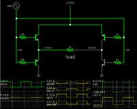
Screenshot of my simplest full H-bridge (in Falstad's animated interactive simulator):


Notice NPN's are at top left, and bottom right.

You can copy the above in whatever simulator you are using.

You may want to substitute mosfets for the transistors.

Even if you don't need a full H-bridge, this illustrates the concept for a half bridge, push-pull, etc.

Or, if you click the link below, it will open the www.falstad.com/circuit website, load my schematic, and run it on your computer.

https://tinyurl.com/b4zfh9t

You can alter values by right-clicking on a component, and selecting Edit.
 
ı simulated the circuit in application note of TL494. It is a buck converter which has 5V output and 32V input. As ı said before, ı have no experience about dc to dc converter. My question is that how ı can modify the control circuit for boost converter or half bridge push pull converter. I have done an inverter with same TL494 but ı dont know how ı can use the TL494 for dc to dc converter.
Draft1.jpgDraft2.jpg
 

Hi ı am both newbie in this forum and power electronics. I have a 1kVA UPS project and ı have some issues about making the DC bus voltage stable 311VDC for getting 220VAC in h-bridge across the MOSFETs. My inverter has approx. 10-11 volts PWM output. I have 36VDC from 3 lead acid battery and ı have to boost the voltage about 311VDC in order to drive MOSFETs. I can do it with 36VDC with conventional 50HZ transformer also but ı dont want the output voltage to decrease while the battery discharges. Is it possible and suitable to boost the voltage in this 1kVA UPS project ? If not, which topology should be chosen in order to make to voltage about 311VDC.

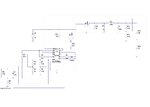

See this example, maybe you will get some idea for your project.

Project address:
**broken link removed**

**broken link removed**


:wink:
 
  • Like
Reactions: doddye

    doddye

    Points: 2
    Helpful Answer Positive Rating
See this example, maybe you will get some idea for your project.

Project address:
**broken link removed**

**broken link removed**


:wink:

Can ı use this IC for 1kVA boost converter or push pull converter. In specifications, it says output power is 350W.
 

Can ı use this IC for 1kVA boost converter or push pull converter. In specifications, it says output power is 350W.

This is example of principe for up 350W, and can be adjusted for various other specifications, but if you dont understand what you doing better dont play with thise things.
 

This is example of principe for up 350W, and can be adjusted for various other specifications, but if you dont understand what you doing better dont play with thise things.

I have already implemented PCB of the inverter,battery charger,controlled rectifier,etc. Now, ı just need to boost the voltage from 36VDC to 311VDC. Do you think how ı can learn these things without playing with them ?
 

I have already implemented PCB of the inverter,battery charger,controlled rectifier,etc. Now, ı just need to boost the voltage from 36VDC to 311VDC. Do you think how ı can learn these things without playing with them ?

Soon good project will showup on EDABoard pure sine wave 2KW 220V 50Hz 48V.
 

For now see first step for inverter, later will come descriptions, pictures and other circuit for H-bridge sine wave. This is DC DC convertor. Daniel approved publishing circuit on EDABoard.

48V DC to 360V DC 2KW SG3525 Ferrite :

2kwdcdc.png

Author is Daniel
http://danyk.cz/


:wink:
 
Last edited:
Status
Not open for further replies.

Similar threads

Part and Inventory Search

Welcome to EDABoard.com

Sponsor

Back
Top