Continue to Site

Welcome to EDAboard.com

Welcome to our site! EDAboard.com is an international Electronics Discussion Forum focused on EDA software, circuits, schematics, books, theory, papers, asic, pld, 8051, DSP, Network, RF, Analog Design, PCB, Service Manuals... and a whole lot more! To participate you need to register. Registration is free. Click here to register now.

[SOLVED] Buck converter frequency correction

Status
Not open for further replies.

mitz

Junior Member level 2
Joined
Dec 30, 2012
Messages
20
Helped
0
Reputation
0
Reaction score
0
Trophy points
1,281
Activity points
1,423
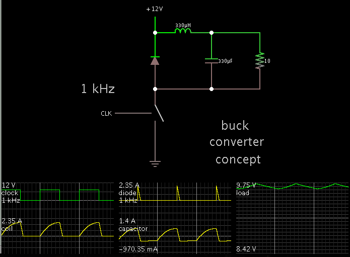
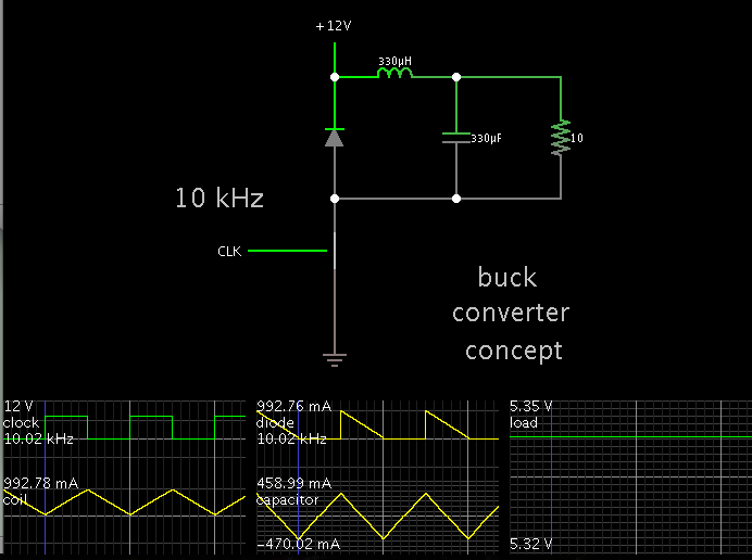
In this buck converter, Voltage reduces with increase in frequency.

PWM 1 kHz, DUTY CYCLE 50% - Voltage around 11.5V

PWM 10 kHz, DUTY CYCLE 50% - Voltage around 5V


PWM is generated with Arduino using tone method (square wave)

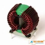
The inductor is toroid type, taken from a 600VA APC UPS. Of the 4 pins, only 2 are connected. (Image attached)
Capacitor tried are 330uF, 200v and 2200uf,60v


Why is increase in frequency reducing voltage.

Frequency need to be increased above audible range.


Would you pls suggest where the problem is.
 

Attachments

  • Toroid Inductor2.jpg
    Toroid Inductor2.jpg
    7.7 KB · Views: 69
  • Buck Converter.jpg
    Buck Converter.jpg
    47.4 KB · Views: 74
Last edited:

I guess, the higher frequency increase ur Inductance impedance and cause voltage drop on it. So voltage somewhere is reduced. (you didn't state where the voltage is reduced.)
 

I don't know what that circuit is but it's not a normal buck converter. Your circuit has the MOSFET switching the complete circuit including the free-wheel diode, the output capacitor, and the load. What that does I have no idea. :?:

A buck converter would have a P-MOSFET in series between the input power and the inductor with the free-wheel diode, output capacitor, and load going to ground.
 

Your circuit works as a buck converter, although it appears unusual in the sense that the load is isolated from either supply rail.

I made simulations of the chief scene of action. (For the load I used a constant resistance, rather than a bulb whose resistance changes dynamically with applied voltage.)

At 1 kHz:


At 10 kHz:


Notice that coil current reaches a higher peak when operating at the lower frequency.

The higher frequency has a shorter switch-On time, hence coil current has less time to build.

Why is increase in frequency reducing voltage.

Frequency need to be increased above audible range.

A buck converter can be operated at a large range of duty cycles, to deliver a desired output V to your chosen load.

It may turn out that your coil needs a lower Henry value, to operate at higher frequencies.
 
  • Like
Reactions: mitz

    mitz

    Points: 2
    Helpful Answer Positive Rating
As shown in Brads simulation (but not analyzed in technical terms), the buck converter changes from DCM (discontinuous conduction mode) to CCM (continuous conduction mode) when increasing the frequency, which changes also the duty cycle to output voltage relation. The expectable "regular" buck converter voltage is

Vout = duty cycle*Vin - Voltage drops

and will be achieved in CCM, at higher frequencies.

In so far the observed behaviour is normal operation.
 

@BradTheRad. Thank you very much for the advice. A hand wound inductor with just 4 turns is almost working with 40KHz. Still there is little HF noise. Does a bigger capasitor like 2200uF, 63V in the output have effect of voltage regulation?

Any help would be very much appreciated.

Also pls advice how you got those nice oscilloscope output in Circuit simulator. Mine is bit junky.
 
Last edited:

@BradTheRad. Thank you very much for help. I tried with few inductors that I got. Almost same results. Instead tried with Arduino's analogWrite's frequency of 490Hz. With variable duty cycle the voltage can be controlled from 1.7V to 12.5V with an input of 13.5V. So far results are satisfactory but the annoying "Ziiiing" oscillation in the ear is very uneasy.

Any help would be very much appreciated.

To reduce audible noise it is common to operate at a frequency above 20 kHz. The coil needs to be a small Henry value.

Also pls advice how you got those nice oscilloscope output in Circuit simulator. Mine is bit junky.

Falstad's simulator allows you to change the position and speed of scope traces. Right-click on the trace and select an option. (With a Mac, press 'control' and click.)

To label scope traces and re-arrange their order, click Export under File menu. You'll edit the component list directly in the window, then Import it.
(You need to remember which trace is for which component. Hover the mouse on a trace. Watch to see which component turns blue.)

For oscilloscope traces, look for lines beginning with 'o', near the end of the list. Here is the scope data from my simulation.


Code Java - [expand]
1
2
3
4
5
o 4 64 0 42 20.0 9.765625E-5 0 -1 clock
o 1 64 0 33 4.374501449566024 11.198723710889022 0 -1 coil
o 2 64 0 41 4.091738259870177 10.474849945267655 1 -1 diode
o 3 64 0 289 4.676805239458889 11.972621413014757 1 -1 capacitor
o 9 64 0 290 5.0 0.4 2 -1 load


To add a label, go to the end of a line, type space and a word such as 'load' or 'clock' or 'capacitor'.

To change their order, cut and paste lines in the desired sequence. You must also do the following step in order to make the traces appear onscreen in the desired order.

The number which is second from the end determines its position onscreen. The leftmost trace is 0.

To stack or unstack, change that number on each line. When multiple lines are stacked, this number will be identical in those lines.

In my example above, the clock and coil are stacked at the left. Their number is 0.
Then the diode and capacitor are stacked. Their number is 1.
The load is last. Its number is 2.
 
  • Like
Reactions: mitz

    mitz

    Points: 2
    Helpful Answer Positive Rating
@BradTheRad. Thanks a lot for spending your valuable time helping me immensly. I tried with just 4 turns on a small hand wound inductor and got good results with frequencies above audible range. Does not a very tight wound coil oscillate?

These days even if I think of the "Ziing" noise I 'hear' it - inside the head. Have any idea? :p

When people report buzz or hum from a coil, the advice is usually to varnish the windings, etc.

The aim is to prevent the wires vibrating side-to-side, in response to magnetic forces, and causing them to 'sing'.
 
  • Like
Reactions: mitz

    mitz

    Points: 2
    Helpful Answer Positive Rating
@BradTheRad. Thank you very much for all help. Good day.
 

Status
Not open for further replies.

Similar threads

Part and Inventory Search

Welcome to EDABoard.com

Sponsor

Back
Top