Prince Vegeta
Member level 5
Hi... I am working at an ATS project (automatic transfer switch) and this program and schematic I used in protesu ISIS kinda gives me some error.
the ATS have 2 input sources (350v peak each) and 1 output which is gonna be one of them.
now the main problem is that it shorts out the 2 sources!
the control program seems fine as I put some indication LEDs and tested it.
Also, it have a AD736 True RMS-to-DC converter which have 1v peak input and outputs a 1v max dc voltage that equals to the rms of the signal.
I tested this IC in proteus and seemed fine.
I will post the schematic and attach the isis project file and MikroC program.
the program is made to activate the source if the ADC value above 117 as I remember.. I used voltage division to achieve needed signals.
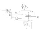
this is the schematic:

____
I hope that you try it and point out what's causing the short circuit (btw, my laptop is old and so simulation sometimes fail).
one important thing: in real-life should i connect a ground to an AC voltage source? I don't think so but simulation can't be done without it.
looking forward to your help.
the ATS have 2 input sources (350v peak each) and 1 output which is gonna be one of them.
now the main problem is that it shorts out the 2 sources!
the control program seems fine as I put some indication LEDs and tested it.
Also, it have a AD736 True RMS-to-DC converter which have 1v peak input and outputs a 1v max dc voltage that equals to the rms of the signal.
I tested this IC in proteus and seemed fine.
I will post the schematic and attach the isis project file and MikroC program.
the program is made to activate the source if the ADC value above 117 as I remember.. I used voltage division to achieve needed signals.
this is the schematic:

____
I hope that you try it and point out what's causing the short circuit (btw, my laptop is old and so simulation sometimes fail).
one important thing: in real-life should i connect a ground to an AC voltage source? I don't think so but simulation can't be done without it.
looking forward to your help.