Continue to Site

Welcome to EDAboard.com

Welcome to our site! EDAboard.com is an international Electronics Discussion Forum focused on EDA software, circuits, schematics, books, theory, papers, asic, pld, 8051, DSP, Network, RF, Analog Design, PCB, Service Manuals... and a whole lot more! To participate you need to register. Registration is free. Click here to register now.

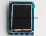
LCD2.4 TFT +Touch+SDRAM

Status
Not open for further replies.

very question

Advanced Member level 4
Joined
Nov 11, 2012
Messages
100
Helped
4
Reputation
8
Reaction score
4
Trophy points
1,298
Location
Iran
Activity points
1,906
Hi dear All
Thank you for your time
I want to use lcd TFT 2.4 with touch in my project
Would you please help me!!
Is there any library for them ?
my microcontroller is lpc1768
Thanks in advance
 

Hello bianchi
my lcd is TFT"2.4" with ILI9325 chip driver
where can i found this library?

Hope this will help :
You should define the port and pin yourself, depends on your chip there....

for example sbit LCD_RS = P0^0 , every uC has different style but nearly the same in my experience,

Good luck...

Code:
void Lcd_Write_Com(char VH,char VL)	 //·¢ËÍÃüÁî
{	
    LCD_RS=0;
	LCD_Writ_Bus(VH,VL);
}


void Lcd_Write_Data(char VH,char VL)	//·¢ËÍÊý¾Ý
{
    LCD_RS=1;
	LCD_Writ_Bus(VH,VL);
}

void Lcd_Init(void)
{

    LCD_REST=1;
    delayms(5);	
	LCD_REST=0;
	delayms(5);
	LCD_REST=1;
	LCD_CS=1;
	LCD_RD=1;
	LCD_WR=1;
	delayms(5);
	

	LCD_CS =0;  //´ò¿ªÆ¬Ñ¡Ê¹ÄÜ
	//************* Start Initial Sequence **********//
	Lcd_Write_Com(0x00,0xE5); Lcd_Write_Data(0x78,0xF0); // set SRAM internal timing
	Lcd_Write_Com(0x00,0x01); Lcd_Write_Data(0x01,0x00); // set SS and SM bit
	Lcd_Write_Com(0x00,0x02); Lcd_Write_Data(0x07,0x00); // set 1 line inversion
	Lcd_Write_Com(0x00,0x03); Lcd_Write_Data(0x10,0x30); // set GRAM write direction and BGR=1.
	Lcd_Write_Com(0x00,0x04); Lcd_Write_Data(0x00,0x00); // Resize register
	Lcd_Write_Com(0x00,0x08); Lcd_Write_Data(0x02,0x07); // set the back porch and front porch
	Lcd_Write_Com(0x00,0x09); Lcd_Write_Data(0x00,0x00); // set non-display area refresh cycle ISC[3:0]
	Lcd_Write_Com(0x00,0x0A); Lcd_Write_Data(0x00,0x00); // FMARK function
	Lcd_Write_Com(0x00,0x0C); Lcd_Write_Data(0x00,0x00); // RGB interface setting
	Lcd_Write_Com(0x00,0x0D); Lcd_Write_Data(0x00,0x00); // Frame marker Position
	Lcd_Write_Com(0x00,0x0F); Lcd_Write_Data(0x00,0x00); // RGB interface polarity
	//*************Power On sequence ****************//
	Lcd_Write_Com(0x00,0x10); Lcd_Write_Data(0x00,0x00); // SAP, BT[3:0], AP, DSTB, SLP, STB
	Lcd_Write_Com(0x00,0x11); Lcd_Write_Data(0x00,0x07); // DC1[2:0], DC0[2:0], VC[2:0]
	Lcd_Write_Com(0x00,0x12); Lcd_Write_Data(0x00,0x00); // VREG1OUT voltage
	Lcd_Write_Com(0x00,0x13); Lcd_Write_Data(0x00,0x00); // VDV[4:0] for VCOM amplitude
	Lcd_Write_Com(0x00,0x07); Lcd_Write_Data(0x00,0x01);
	delayms(50); // Dis-charge capacitor power voltage
	Lcd_Write_Com(0x00,0x10); Lcd_Write_Data(0x10,0x90); // 1490//SAP, BT[3:0], AP, DSTB, SLP, STB
	Lcd_Write_Com(0x00,0x11); Lcd_Write_Data(0x02,0x27); // DC1[2:0], DC0[2:0], VC[2:0]
	delayms(50); // Delay 50ms
	Lcd_Write_Com(0x00,0x12); Lcd_Write_Data(0x00,0x1F); //001C// Internal reference voltage= Vci;
	delayms(50); // Delay 50ms
	Lcd_Write_Com(0x00,0x13); Lcd_Write_Data(0x15,0x00); //0x1000//1400   Set VDV[4:0] for VCOM amplitude  1A00
	Lcd_Write_Com(0x00,0x29); Lcd_Write_Data(0x00,0x27); //0x0012 //001a  Set VCM[5:0] for VCOMH  //0x0025  0034
	Lcd_Write_Com(0x00,0x2B); Lcd_Write_Data(0x00,0x0D); // Set Frame Rate   000C
	delayms(50); // Delay 50ms
	Lcd_Write_Com(0x00,0x20); Lcd_Write_Data(0x00,0x00); // GRAM horizontal Address
	Lcd_Write_Com(0x00,0x21); Lcd_Write_Data(0x00,0x00); // GRAM Vertical Address
	// ----------- Adjust the Gamma Curve ----------//
	Lcd_Write_Com(0x00,0x30); Lcd_Write_Data(0x00,0x00);
	Lcd_Write_Com(0x00,0x31); Lcd_Write_Data(0x07,0x07);
	Lcd_Write_Com(0x00,0x32); Lcd_Write_Data(0x03,0x07);
	Lcd_Write_Com(0x00,0x35); Lcd_Write_Data(0x02,0x00);
	Lcd_Write_Com(0x00,0x36); Lcd_Write_Data(0x00,0x08);//0207
	Lcd_Write_Com(0x00,0x37); Lcd_Write_Data(0x00,0x04);//0306
	Lcd_Write_Com(0x00,0x38); Lcd_Write_Data(0x00,0x00);//0102
	Lcd_Write_Com(0x00,0x39); Lcd_Write_Data(0x07,0x07);//0707
	Lcd_Write_Com(0x00,0x3C); Lcd_Write_Data(0x00,0x02);//0702
	Lcd_Write_Com(0x00,0x3D); Lcd_Write_Data(0x1D,0x04);//1604
	
	//------------------ Set GRAM area ---------------//
	Lcd_Write_Com(0x00,0x50); Lcd_Write_Data(0x00,0x00); // Horizontal GRAM Start Address
	Lcd_Write_Com(0x00,0x51); Lcd_Write_Data(0x00,0xEF); // Horizontal GRAM End Address
	Lcd_Write_Com(0x00,0x52); Lcd_Write_Data(0x00,0x00); // Vertical GRAM Start Address
	Lcd_Write_Com(0x00,0x53); Lcd_Write_Data(0x01,0x3F); // Vertical GRAM Start Address
	Lcd_Write_Com(0x00,0x60); Lcd_Write_Data(0xA7,0x00); // Gate Scan Line
	Lcd_Write_Com(0x00,0x61); Lcd_Write_Data(0x00,0x01); // NDL,VLE, REV
	Lcd_Write_Com(0x00,0x6A); Lcd_Write_Data(0x00,0x00); // set scrolling line
	//-------------- Partial Display Control ---------//
	Lcd_Write_Com(0x00,0x80); Lcd_Write_Data(0x00,0x00);
	Lcd_Write_Com(0x00,0x81); Lcd_Write_Data(0x00,0x00);
	Lcd_Write_Com(0x00,0x82); Lcd_Write_Data(0x00,0x00);
	Lcd_Write_Com(0x00,0x83); Lcd_Write_Data(0x00,0x00);
	Lcd_Write_Com(0x00,0x84); Lcd_Write_Data(0x00,0x00);
	Lcd_Write_Com(0x00,0x85); Lcd_Write_Data(0x00,0x00);
	//-------------- Panel Control -------------------//
	Lcd_Write_Com(0x00,0x90); Lcd_Write_Data(0x00,0x10);
	Lcd_Write_Com(0x00,0x92); Lcd_Write_Data(0x06,0x00);
	Lcd_Write_Com(0x00,0x07); Lcd_Write_Data(0x01,0x33); // 262K color and display ON
	LCD_CS =1;  //¹Ø±ÕƬѡʹÄÜ

}
 
thanks for you reply
i need schematic for how this type of lcd pins connect to microcontrollers
 

thanks for you reply
i need schematic for how this type of lcd pins connect to microcontrollers

That's very easy....
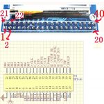
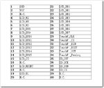
Hope this pin assigment will help....
Anyway do you have the LCD itself in your hand ?
Because it's a waste of time if you wanna create yourself, many are sold out there...
 

Attachments

  • 40 pins 2.4 inch LCD.jpg
    40 pins 2.4 inch LCD.jpg
    102.5 KB · Views: 151
yes I have it,I want example of that

I don't know what kind of pin configuration there, you need to find yourself, usually it's written on the board the pin function..

- - - Updated - - -

can you show me the photo ? so I can see ?
 

Hi
I found this Pin Description but I don't know is it true or not?
which pins for touch screen?
500px-Pin_definition_2.4TFT01.jpg
 

hello ;
please anyone have a schematic for tft lcd with pic ??((how can i connect it with pic please help me ))
 

Finally I run lcd and you can see my program in continue
View attachment TFTLCD.rar

Now I want to work on it's screen touch,the driver of that is XPT2046
would you please help me??
 

I want to use rtc in cmsis but I faced with this error
linking...
flash_fs.axf: Error: L6218E: Undefined symbol CLKPWR_ConfigPPWR (referred from lpc17xx_rtc.o).
flash_fs.axf: Error: L6218E: Undefined symbol check_failed (referred from lpc17xx_rtc.o).
 

Status
Not open for further replies.

Similar threads

Part and Inventory Search

Welcome to EDABoard.com

Sponsor

Back
Top