Continue to Site

Welcome to EDAboard.com

Welcome to our site! EDAboard.com is an international Electronics Discussion Forum focused on EDA software, circuits, schematics, books, theory, papers, asic, pld, 8051, DSP, Network, RF, Analog Design, PCB, Service Manuals... and a whole lot more! To participate you need to register. Registration is free. Click here to register now.

Alcohol Detector using MQ2 and PIC 18f452 or PIC18f4620

Status
Not open for further replies.

aistruckz

Newbie level 4
Joined
Feb 14, 2013
Messages
5
Helped
0
Reputation
0
Reaction score
0
Trophy points
1,281
Activity points
1,314
hello,
im a student of computer engineering and im on my final year which we do have and implementation of our proposed project...it is entitled ALCOHOL DETECTION SYSTEM FOR CARS WITH GPS TRACKER..

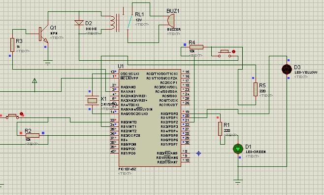
my problem is on its schematic..please help me about the schematic diagram from the sensor to the pic18f452 or pic18f4620...
the process is this,when the driver is detected drunk using the mq2 gas alcohol sensor it will buzz which indicates a drunk driver then it will send an sms notification to the gps tracker..
in connection with this..i only need the schematic from the sensor,buzzer to the pic then to the cellphone...hope u'll help me about this...thank u very much:razz:
 

Attachments

  • MQ-2.pdf
    55.2 KB · Views: 154

As far as I see, sensor connection nodes are H, H, A,A, B,B. Well, one of the H terminal is connected to +5V. another H terminal to Gnd. Both A terminals are tied to +5V. One B of terminals is pulled down by a resister with some value like 5kOhm or you can put trimmer. And another B terminal is connected to microcontroller input pin. I hope that will help progress your project. Good luck.
 
..it helped me,,,i already made a connection on the sensor,,my problem now is the connections from sensor to the pic..where it will be connected...

thank u:grin:
 

As I said, B terminal is connected to ADC of PIC. For PIC18F452, you can connect to one of the pin of PORTA.
 
Still have a problem in my circuit and program using c in mikroC compiler.
 

have you set PORTA pin to analog? please show us ur code if you are ok with it.
 

as of now, i'm still practicing because i really don't have any idea of how to make my circuit,i have a lot of ideas sinking and when i'm making my circuit for my hardware i don't know where i'm gonna put other devices like relays, transistors, diode..like setting PORTA pin to analog..

this are sample code and the circuit im practicing to do:


i don't know if the connections are correct..
 

I do not see gas sensor in your circuit. As I mentioned, gas sensor output should be connected to pin 2 (which is PORTA RA0). In software, you should declare RA0 as analog using ADCON. As a first step, you should make sure your gas sensor interface is working.
 

is this what you've said?
 

Attachments

  • ADS.JPG
    ADS.JPG
    33.9 KB · Views: 131

Status
Not open for further replies.

Part and Inventory Search

Welcome to EDABoard.com

Sponsor

Back
Top