Continue to Site

Welcome to EDAboard.com

Welcome to our site! EDAboard.com is an international Electronics Discussion Forum focused on EDA software, circuits, schematics, books, theory, papers, asic, pld, 8051, DSP, Network, RF, Analog Design, PCB, Service Manuals... and a whole lot more! To participate you need to register. Registration is free. Click here to register now.

varactor values for tuning in a dual band antenna

Status
Not open for further replies.

p2vimal

Newbie level 2
Joined
Feb 18, 2013
Messages
2
Helped
0
Reputation
0
Reaction score
0
Trophy points
1,281
Activity points
1,299
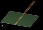
we have prepared an antenna using copper plates, wherein the radiating element is 5x85mm,groundplate is 80x80mm and in between radiating element and groundplate there is a gap of 0.6mm.(air as dielectric)
however we want to incorporate tuning into this using a varactor. How do we go abt it? when we connect a DC circuit,what values of capacitor ,resistors or varactors do we use.?
thanks :)
 

Maybe not yet enough information.
I am imagining a flat strip of copper (how thick?) hanging 0.6mm over a groundplane.
Is it one end at the groundplane, with the strip standing up like a little whip antenna?
etc.
 
From the description it sounds like a 1/4 wave vertical above a square ground plane and would naturally resonate at about 880MHz. What concerns me is calling it a "radiating element". If it's being used for transmission you have to be very careful if you introduce diodes into the circuit because it's very easy to destroy them and the resulting mismatch can destroy the transmitter as well. There is also a risk of serious harmonic interference being caused.

If you do want to tune it, the configuration depends on whether you want to increase or decrease it's effective length. To decrease it, connect the varactor in series with the feed point and provide a DC return from the element to the ground. To increase it's effective length, connect the varactor between the element and ground and apply DC to it through a choke.

Brian.
 
About "tuning" antennas.
What concerns me is calling it a "radiating element". If it's being used for transmission you have to be very careful if you introduce diodes into the circuit because it's very easy to destroy them and the resulting mismatch can destroy the transmitter as well. There is also a risk of serious harmonic interference being caused.
Brian.

Brian went where I hesitated to go.
Sure, some tuning can be done, but only in limited fasion. Most interaction between an antenna structure and the connected electronics involves matching parts, transmission lines, and the like.

The "tuning" of the antenna is mostly decided by its electrical length, which need not be the same as the length of the bit that radiates. An element like we have in mind will have a natural resonance, which can be modified by adding inductance at the feedpoint (loading coil), or capacitance, as Brian suggests, or a bit of both, making a tunable thing.

In either case, this is not the place to put non-linear things like diode semiconductors with a voltage limitation.

So I am thinking we maybe still misunderstand what you have in mind..
 
1stly ...thanks alot for replying,we were hit by a roadblock till ul replied.
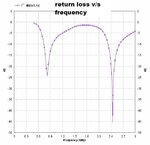
This is a college project.Wherein we are building a dual band monopole antenna.We will test this by connecting to a spectrum analyser,which will show 2 notches at the frequency around 900MHz and 2.4GHz.By tuning, we aim to shift the frequency notches.Im attaching pics of the obtained results. retrn loss vs freq.JPG

- - - Updated - - -

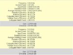
Im also attaching the screen shots of the radiation parameters obtained and the Geometry.
parameters.JPGgeometry.JPG

- - - Updated - - -

Im also attaching the screen shots of the radiation parameters obtained and the Geometry.
parameters.JPGgeometry.JPG
 

Status
Not open for further replies.

Part and Inventory Search

Welcome to EDABoard.com

Sponsor

Back
Top