Vermes
Advanced Member level 4
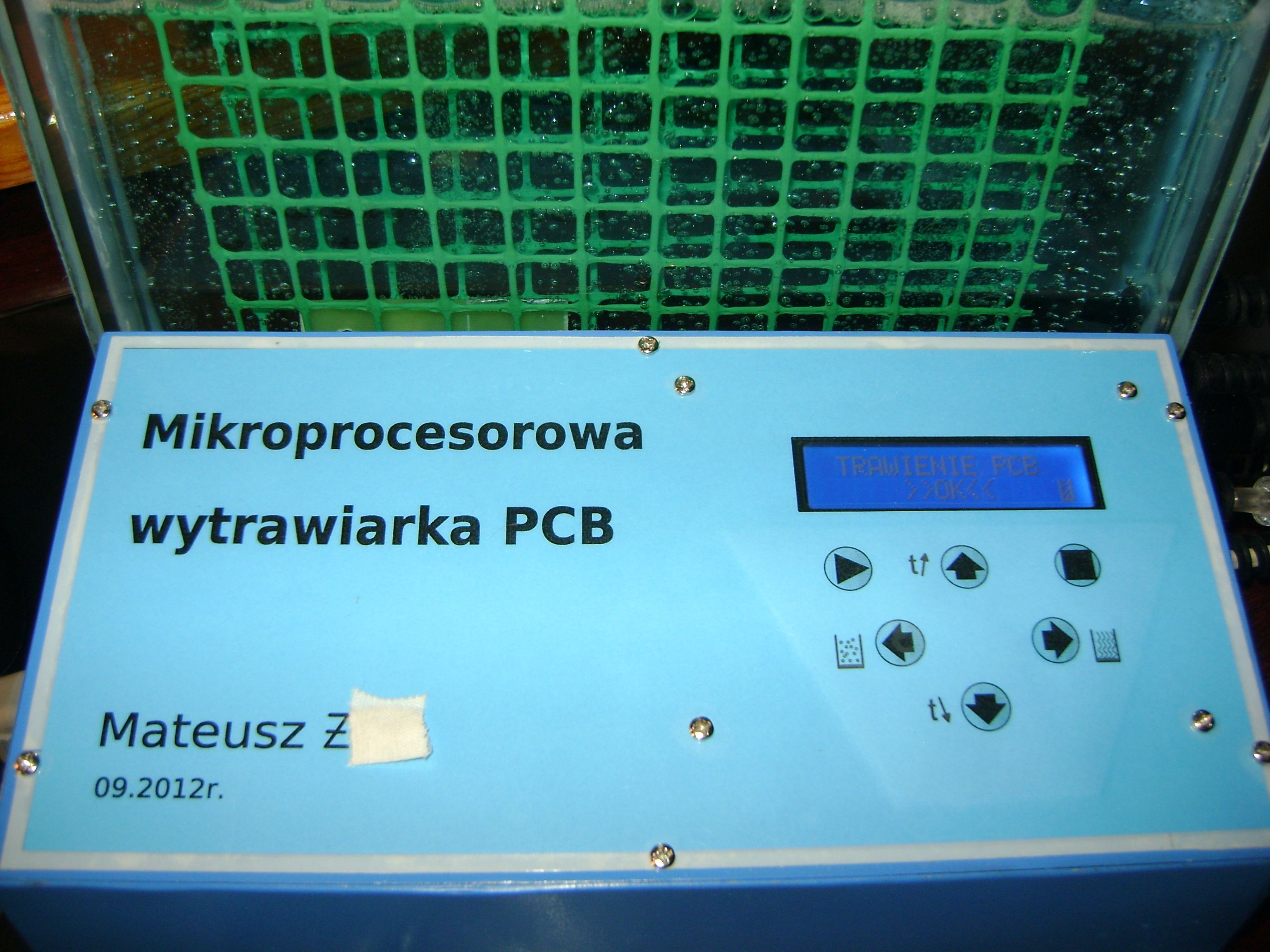
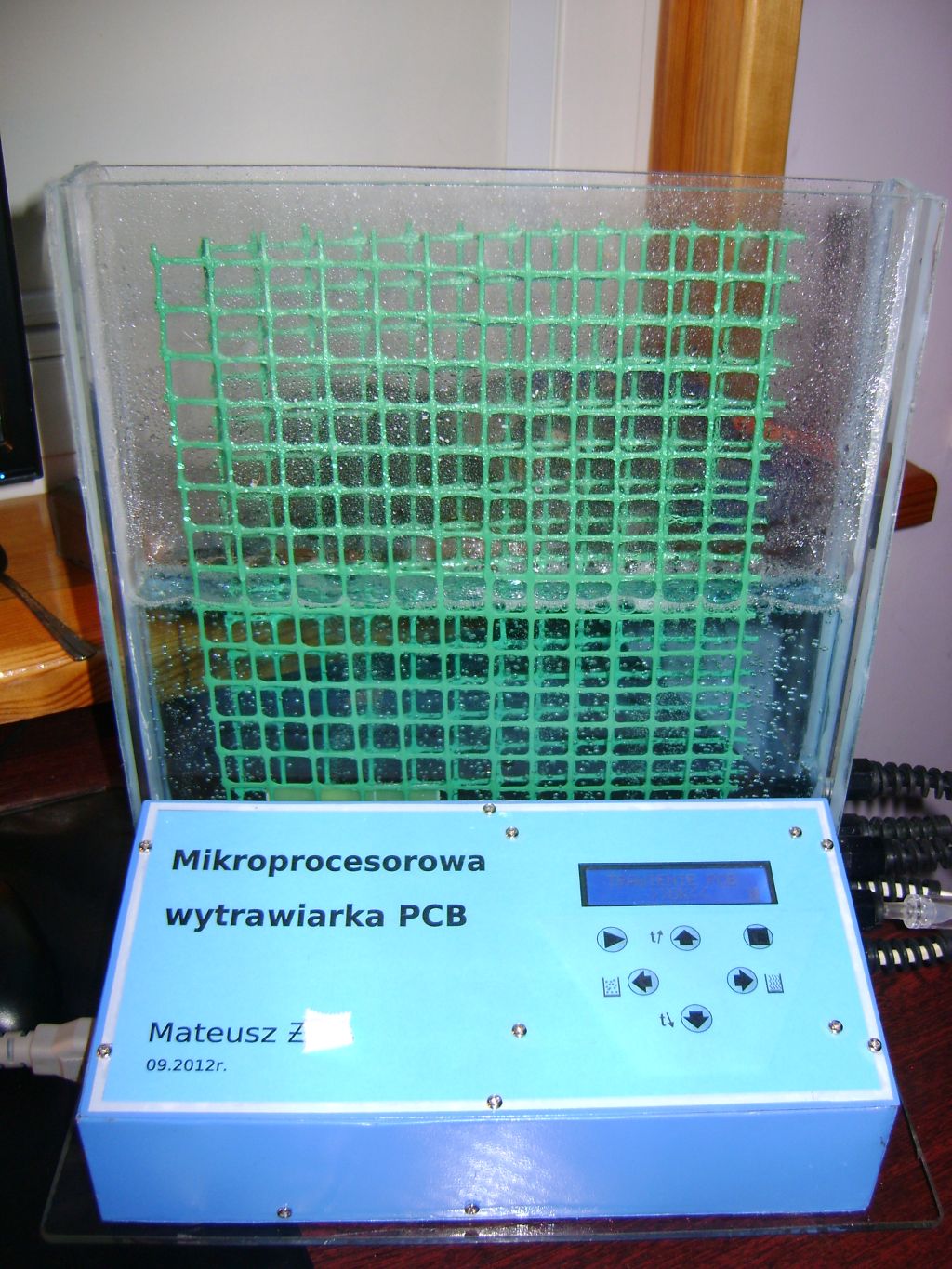
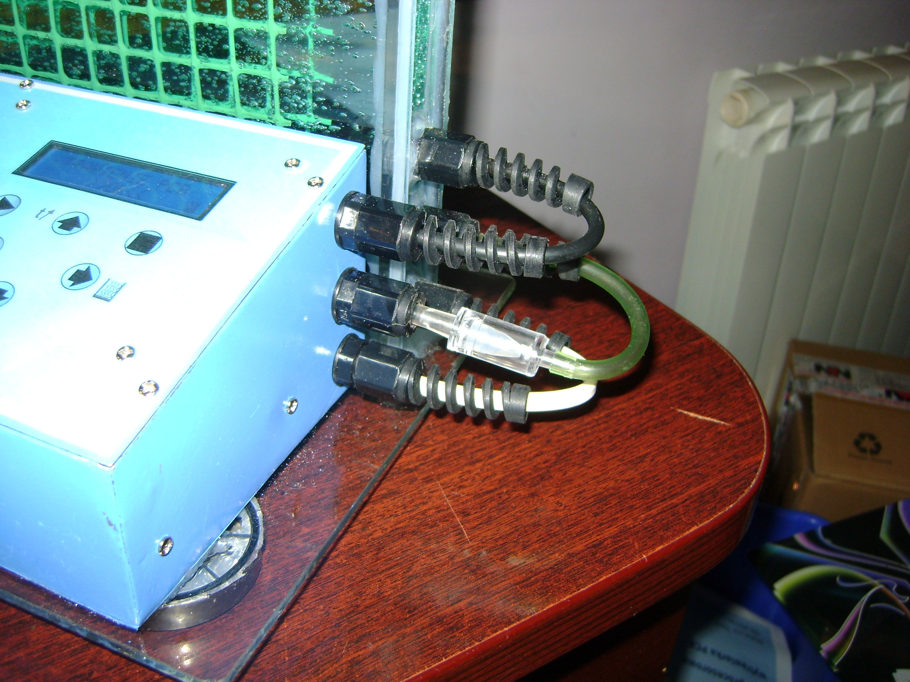
It is a microprocessor PCB etching tank.
As for the tank without the electronic part:
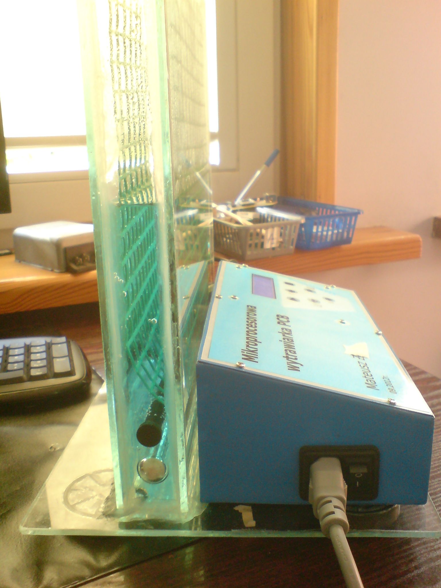
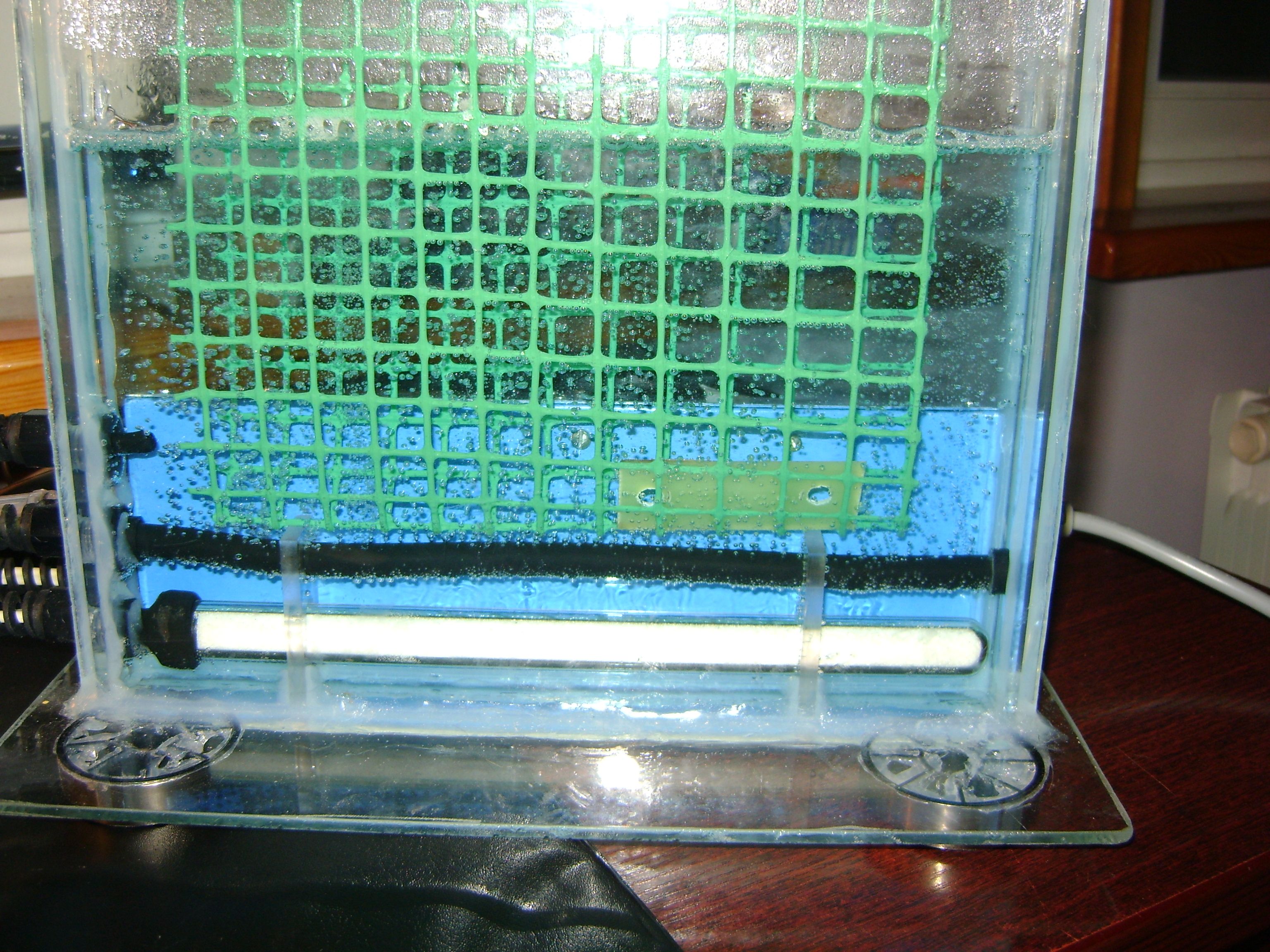
4mm glass was cut to order. The dimensions of this tank are: 300x255x30mm so as A4 fits this. All the cables go to the side. Holes in the glass were made using a grinder with milling cutter. A hole should be made within approximately 15 minutes. Milling can be made in a container of water (the whole element immersed in water).
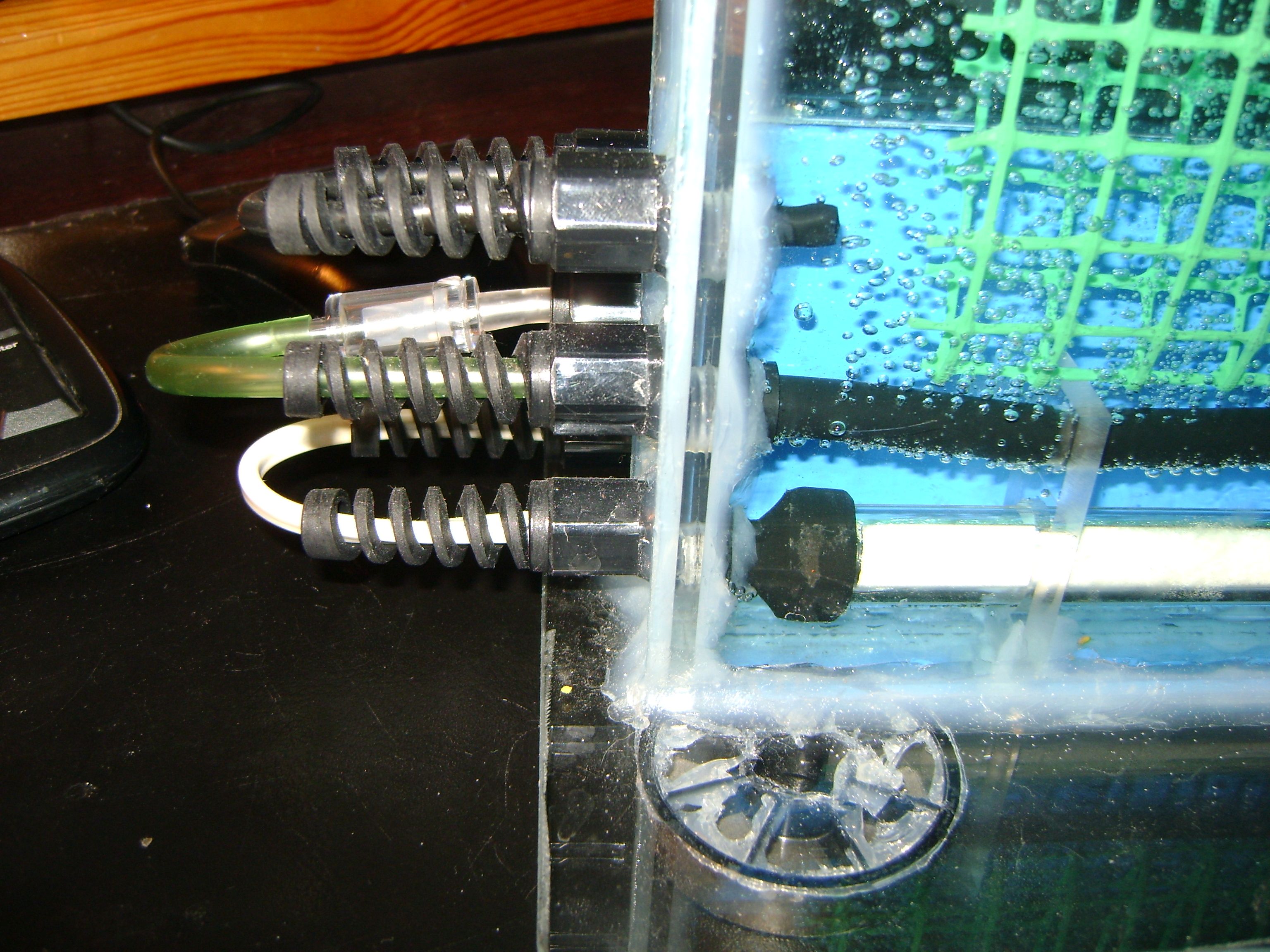
All the elements were glued together using special glue for aquarium appliances which is perfect for this use. Cable glands have to be covered with silicone and screwed through the wall. Feet of the device should be glued to the base.
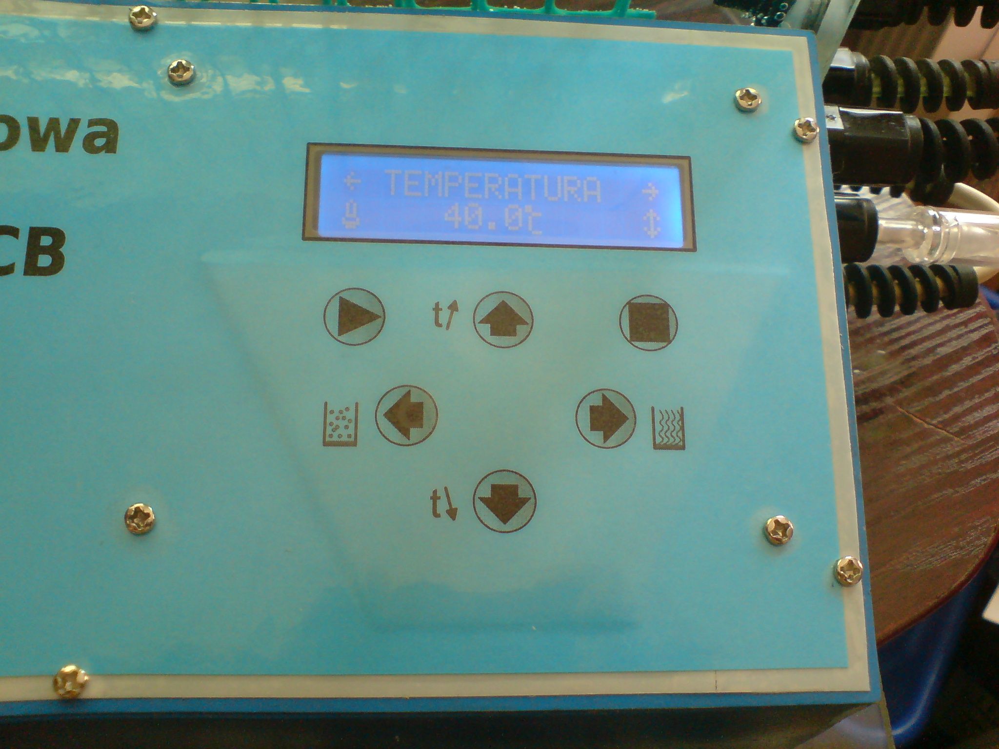
The heater should fit perfectly the tank. Solution, depending on the volume, heats up within 15 minutes to 45 degrees Celsius.
Aerator can be taken from an aquarium, remember that it should have the appropriate size to fit the housing. Additionally you have to add an aerating flexible hose. The lead wire should be removed from the inside. In order to prevent the hose from being lifted and bent under the influence of pumping air, a thin rod made of laminate should be slipped inside it. This could be a sanded part of the frame of a tent.
You will also need a check valve. Be careful, because there are different types and some of them just do not work or stop working after a time (etching damages the spring in the middle).
The whole – hose and heater – should be placed in a construction made of plexiglass and glued to the bottom.
Metal housing can be easily made at home. The one presented in this design was an old computer housing. When you do not have a bender, all the bending can be cut using a sander and then bent in a vice. Then links of the housing can be welded by a welder (for example, made of a microwave transformer). Next, it was painted with spray.
Front panel was printed on blue paper. It was then laminated and glued to the plate. The keyboard consists of microswitches with a “spacer” glued above them. It is high enough so that the buttons do not press themselves.
PCBs are immersed in a solution in the grid of plastic. It is a simple and practical idea.
And now the electronic part:
Program was written in C for Atmega8. It occupies approximately 90-95% of memory. Thermometer on DS18B20, partially covered with silicone and enclosed in a therm-shrinkable pipe. In an emergency, you can release the cable glands and replace the element. The functionality is the best shown in the video. Poor contrast of the display is due to the thin film, in fact the subtitles are very sharp.
A network zero detector is on the board. Switching on occurs at crossing the zero. In the phase of tests (without the phase detector), processor used to restart.
Triacs for the heater are more powerful than BT136 (8A, 600V). Although nothing gets warm, it is good to use a heat sink, just in case. Triacs have to be lied, because when the housing is closed, there is only 10mm of space left.
The PCB was designed in KiCad.
Safety fuse 3A, housing connected with a safety pin in the socket.
If the sheet metal for front panel turns out to be too flexible, you can use a piece of laminate as reinforcement/mounting of the PCB/mounting of the keyboard buttons.
Pictures:
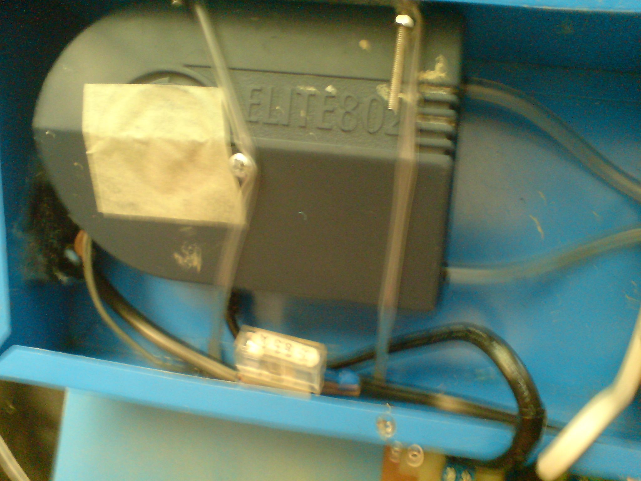
View of the inside. Mounting of the aerator is flexible. In every place between the housing and the pump there is rubber or foam.
The picture of PCB shows how the triac feet should be bent to be in adequate places.
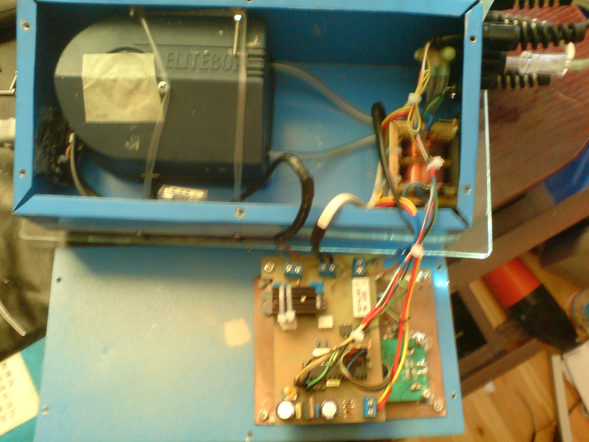
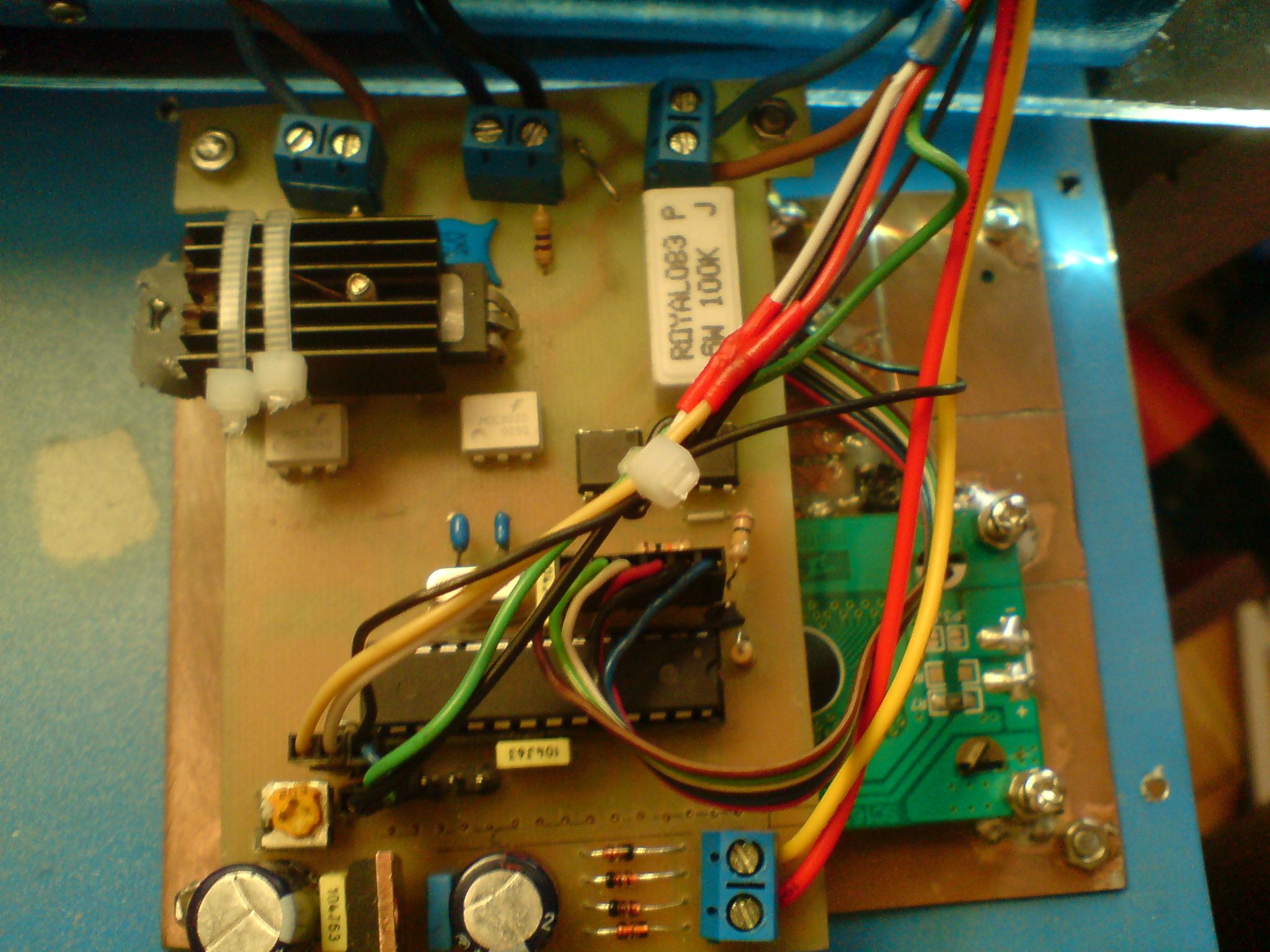
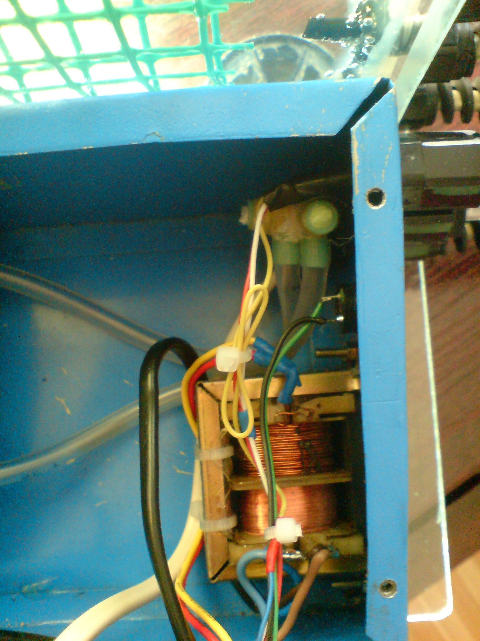
Small transformer to supply the driver.
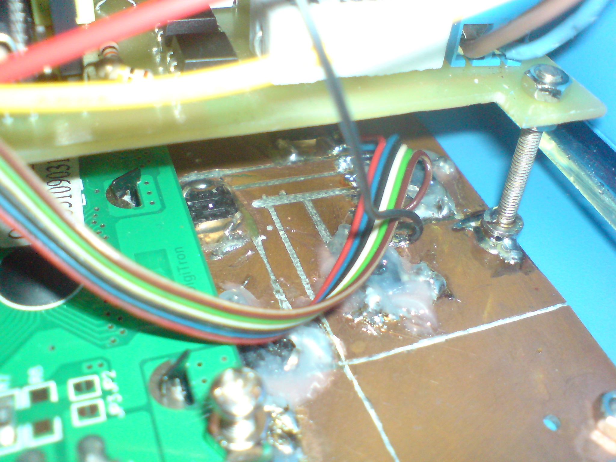
These pictures also show the PCB with buttons from the side of keyboard. Microswitches are soldered and additionally glued to the laminate.
And the video:
Link to original thread (useful attachment) - **broken link removed**