Continue to Site

Welcome to EDAboard.com

Welcome to our site! EDAboard.com is an international Electronics Discussion Forum focused on EDA software, circuits, schematics, books, theory, papers, asic, pld, 8051, DSP, Network, RF, Analog Design, PCB, Service Manuals... and a whole lot more! To participate you need to register. Registration is free. Click here to register now.

[SOLVED] Very high DC differential gain measurement

Status
Not open for further replies.

Junus2012

Advanced Member level 5
Joined
Jan 9, 2012
Messages
1,552
Helped
47
Reputation
98
Reaction score
53
Trophy points
1,328
Location
Italy
Activity points
15,235
Dear friends

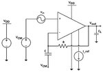
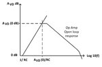
Before I have posted a thread about how to measure the AC open loop characteristics using the attached circuit and graph. these are from Allen Holberg and Jackob Baker

My teacher has told me that this circuit is not suitable for showing the DC gain if it is very high like 100 dB or something like that. this is due to the impossibility for finding real signal source that can provide us with micro volts . Using a divider resistor to drop a voltage in mV from a signal source can add huge amount of noise to the input

Therefore, I must find an alternative method for testing only the DC gain of the op-amp

I am looking for your discussion

Thank you very much
 

Attachments

  • AC.jpg
    AC.jpg
    289.9 KB · Views: 123
  • response.jpg
    response.jpg
    235 KB · Views: 104
Last edited:

Dear Friends, I searched further but I didnt find an alternative method except for the on-wafer measurement which is impossible in pcb board
 

Dear Friends, thank you for your participation in my thread, I have found a very good document to do easily most of the measurement setup

I attached it here

Regards
 

Attachments

  • two_stg_char.pdf
    100.2 KB · Views: 97

So basically you are just running the device in a closed loop and measuring Ao by dividing the output by the sjn voltage. The accuracy of your results will weigh heavily on the accuracy of your 500v/v amplifier. and if this is for measuring open loop of a high dc gain amp, say for example 100dB, thats a gain of 100e3, and so that means that your sjn will be 100e3 smaller then your output voltage...to give you you an idea that means if you were testing a 100dB OL gain amp whos max output is say 3.3V and linear Vout/Vin is good only to 3.0V then while running the ac gain from Vin to vout to achieve 3.0V your sjn would be 30uV, gaining this by 500 gives you 15mV(if your measurement accuracy is say 1mV you could be off by 7%. and with such a large cl gain it will be hard to assert the gain is exactly 500 with great accuracy in the ac realm). As a check I would measure the closed loop gain (much easier to measure) then measure the feedback beta(also easy to measure), you can do this easily by placing vsource with some frequency on the output and measure that voltage at the summing junction this will be more like a gain of .3 to .6(easier to deal with then the 100kish stuff) or so then use the simple cl equation Acl= Aol/(1+B*Aol) this will be much more accurate I think since your measurements are much more simple.
-Pb

- - - Updated - - -

the Acl i gave was for inverting
 
Hello prestonee

Thank you for your response

No, this setup is to solve the problem of the very small signal source related to the testing of very high gain op-amp . Why, I will tell you

because I am not going to measure the gain from the output to the signal source in the setup I attached you before. the open loop gain is being measured by dividing the output voltage to the differential voltage VID of the DUT op-amp. since VID is very small, it is amplified by the instrumentation amplifier 500 times before using it, hence you have to divide the result by 500.

the author has used the instrumentation amplifier because he used the DUT in non-inverting connection which lead to have a common mode voltage signal. otherwise if you use an inverting connection, then you can use an inverting amplifier for the auxiliary amplifier as well

Again, I agree with you that the auxiliary amplifier gain of 500 is pretty large, therefore I think 100 is more suitable.
 

I understand this, Just worry that you might transform your issue from creating a very small source to trying to measure a very small number(without distorting it).
Even my loopgain approach has this fault, you would need to run the closed loop output through a gain of 100(meaning the closed loop gain would be very small, maybe 1/100 to get the accuracy needed for a 100dB amp, which again runs into the possibility of distorting while gaining.
You may use multiple methods to see if you can find agreement between them.

I wish you luck Junus (I hate having to use experiments to verify theory with high precision, too many limitations and non-ideality crop up)
,Pb
 
Thank you very much prestonee

I understand this, Just worry that you might transform your issue from creating a very small source to trying to measure a very small number(without distorting it).
Even my loopgain approach has this fault, you would need to run the closed loop output through a gain of 100(meaning the closed loop gain would be very small, maybe 1/100 to get the accuracy needed for a 100dB amp, which again runs into the possibility of distorting while gaining.
You may use multiple methods to see if you can find agreement between them.

I wish you luck Junus (I hate having to use experiments to verify theory with high precision, too many limitations and non-ideality crop up)
,Pb
 

Status
Not open for further replies.

Part and Inventory Search

Welcome to EDABoard.com

Sponsor

Back
Top