Continue to Site

Welcome to EDAboard.com

Welcome to our site! EDAboard.com is an international Electronics Discussion Forum focused on EDA software, circuits, schematics, books, theory, papers, asic, pld, 8051, DSP, Network, RF, Analog Design, PCB, Service Manuals... and a whole lot more! To participate you need to register. Registration is free. Click here to register now.

Phase accumulator for a DDS in FPGA

Status
Not open for further replies.

nanostallmann

Newbie level 5
Joined
Jan 3, 2013
Messages
8
Helped
0
Reputation
0
Reaction score
0
Trophy points
1,281
Activity points
1,345
Hi all,
I have a question about a phase accumulator that I'm doing for implement a DDS in an ATLYS board (SPARTAN6).
The phase accumulator that I wrote works with a input 18bit phase_word_width and outputs a 10bit address to a RAM block.

When I set a phase word that set integer or fractional part (ie: 000000001000000000 or 000100000000000000 or 000000000010000000)
the accumulator outputs the values with constant increment (ie: 2 each clock period, 64 each clock period or 1 every two clock period for the ie above).
When I set a phase word that set either integer and fractional part ( ie: 000000000110000000) the accumulator outputs the sequence with variable increment (ie: one time with 1 increment and 1 time with 2 increment).
Mathematically I think is ok! but the question is:
When I change the phase with variable increment the wave will not distorted by spurs generated by this behavior???

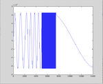
For clarity there are some simulation screen-shoots (the example above don't respect the simulation values):

1.png
2.png
3.png
4.png

I think that one solution could be interpolate the output values... what your opinion about this ??
Thank you
 
Last edited:

Hi all,
I have elaborate the simulation results obtainated after then I wired the phase accumulator with the ROM (that contain the wave values) and the results not appear affetct by any form of spurs (naturally is present quantization error).
I attach the results:
 

Attachments

  • Results.png
    Results.png
    19 KB · Views: 118
Last edited:

Both phase and magnitude quantization are creating spurs in the DDS signal. Phase and magnitude resolution have to be chosen according to the intended signal performance.

The phase jitter can't be reduced by interpolation, I think. But the spurs can be more smoothly distributed by dithering algorithms.

Can you tell me about how to relate these parameters (or can you suggest me where can I find this info)?
Thanks
 
Last edited:

Can you tell me about how to relate these parameters (or can you suggest me where can I find this info)?

A nice paper on the subject is this one:

**broken link removed**

18 bit phase accu with 10 bit DAC strikes me as a bit spurry, but it really would depend on your requirements. Anyways, increasing the resolution of your phase accu is a pretty cheap way to improve things somewhat. Depending on how fast the DAC is you can employ some dithering scheme. Oh and another way to improve things is to use for example a Taylor series for correction. Now that I mention it, at least the Xilinx DDS core has the Taylor series feature on. I would suspect Altera has that as well, but I'm not sure.

Anyways, if you haven't done so already I suggest checking out the DDS core from your favorite vendor. If only for a bit of inspiration.
 

10 Bit phase and magnitude resolution is a reasonable range for medium quality NCOs, e.g. used with sine inverters or active front ends. For test and mesurement 16 bit or better can be appropriate.

The exact relation between phase/magnitude resolution and analog performance, e.g. SFDR (spurious free dynamic range) is a rather complex numerical problem. Mostly it's determined in simulations. The Altera NCO MegaFunction is e.g. providing a simulated time domain and spectral response.
 

A nice paper on the subject is this one:

**broken link removed**

18 bit phase accu with 10 bit DAC strikes me as a bit spurry, but it really would depend on your requirements. Anyways, increasing the resolution of your phase accu is a pretty cheap way to improve things somewhat. Depending on how fast the DAC is you can employ some dithering scheme. Oh and another way to improve things is to use for example a Taylor series for correction. Now that I mention it, at least the Xilinx DDS core has the Taylor series feature on. I would suspect Altera has that as well, but I'm not sure.

Anyways, if you haven't done so already I suggest checking out the DDS core from your favorite vendor. If only for a bit of inspiration.

The phase accuracy is limited to 18bit only for avoid to wait for long time simulation in debug phase (in which am I), the target is 48bit for phase accumulator and probably 18bit for the DAC.
Thank for the tips ... I have read yet something about CORDIC alg. and Taylor series approach....
I will read the papers...
 

Status
Not open for further replies.

Part and Inventory Search

Welcome to EDABoard.com

Sponsor

Back
Top