Continue to Site

Welcome to EDAboard.com

Welcome to our site! EDAboard.com is an international Electronics Discussion Forum focused on EDA software, circuits, schematics, books, theory, papers, asic, pld, 8051, DSP, Network, RF, Analog Design, PCB, Service Manuals... and a whole lot more! To participate you need to register. Registration is free. Click here to register now.

Phase margin simulationt from the buffer connection

Status
Not open for further replies.

Junus2012

Advanced Member level 5
Joined
Jan 9, 2012
Messages
1,552
Helped
47
Reputation
98
Reaction score
53
Trophy points
1,328
Location
Italy
Activity points
15,235
Dear friends

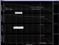
I am trying to compare the ohase margin I usually simulate from the open loop with the phase margin that I wanna find from the buffer connection.

from the basic difintion of the phase margin, it is the difference in the output phase from 180 at when the GBW=0 dB. As you can see from the image I attached the phase margin is different from the two setting unless if I am wrong

looking forward for you reply
Regards


The second magnitude/phase diagram is apparently showing a closed loop transfer characteristic. Although the closed loop can be derived from the open loop frequency characteristic, the phase hasn't the meaning of a phase margin. What do you exactly want to compare?

The general expression of the (complex) closed loop transfer characterictic Acl of a feedback amplifier with open loop gain Aol and feedback factor f is given as
Acl = Aol/(1 + Aol*f)

f is unitity in case of the buffer amplifier.
 
Hi Junus,
complementary to FvM`s reply I like to remind you on the phase margin definition:

The phase margin applies to the loop gain of a system with feedback (remember: loop gain is the gain of the open loop).
Thus, it depends on the feedback factor and is worst for maximum feedback of 100% (as in your case).
Here we have a feedback factor of "1" which means: Loop gain identical to the opamp´s open loop gain Ao.
Thus, only the first graph of your attachement gives the correct phase margin (for the worst case, which is buffer operation).
The 2nd graph gives gain and phase of the closed-loop system.
It looks interesting - but does not tell you something about the margin (just a rough estimate as indicated by gain peaking).
 
Thank you very much FvM and LvW.

As I understand from you, the first graph is the correct one to simulate the phase margin.

LvW: I understood your post completely, except this part "remember: loop gain is the gain of the open loop".
but the loop gain is 1+BAo which you later told.

Any way, if I would use the op-amp to work with gain of 20 for example, in this case do I need to measure the phase margin from the worst case (of buffer connection) or according to the used gain.

Thank you again


FvM
Hi Junus,
complementary to FvM`s reply I like to remind you on the phase margin definition:

The phase margin applies to the loop gain of a system with feedback (remember: loop gain is the gain of the open loop).
Thus, it depends on the feedback factor and is worst for maximum feedback of 100% (as in your case).
Here we have a feedback factor of "1" which means: Loop gain identical to the opamp´s open loop gain Ao.
Thus, only the first graph of your attachement gives the correct phase margin (for the worst case, which is buffer operation).
The 2nd graph gives gain and phase of the closed-loop system.
It looks interesting - but does not tell you something about the margin (just a rough estimate as indicated by gain peaking).
 

Any way, if I would use the op-amp to work with gain of 20 for example, in this case do I need to measure the phase margin from the worst case (of buffer connection) or according to the used gain.

Then you should check the phase margin as in the first graph, but at the frequency where the gain is 20.
 
LvW: I understood your post completely, except this part "remember: loop gain is the gain of the open loop".
but the loop gain is 1+BAo which you later told.

Did I ? Where and when?

The loop gain is AL=beta*Ao (feedback factor*open loop gain).
When beta=1 you arrive at AL=Ao.
 
Yes, by this case it is right as already mentioned before , any way I got what you want to tell.

please, I also have asked about if the gain is 20 for just as an example. lamoun has suggested me in this case that I the phasemargin here is relagted at the gain = 20 not at the 0 dB.
for me I am thinking that still the phase margin at 0dB is our interest because of the input signal frequency can make the gain of the amplifier drop at this point.

However I am not sure so I need you opinion in this case

Thanks alot


Did I ? Where and when?

The loop gain is AL=beta*Ao (feedback factor*open loop gain).
When beta=1 you arrive at AL=Ao.
 

The question has been already answered in post #3. You'll determine phase margin for the feedback factor of the 20 dB amplifier (which is 0.1).
 

please, I also have asked about if the gain is 20 for just as an example. lamoun has suggested me in this case that I the phasemargin here is relagted at the gain = 20 not at the 0 dB.
for me I am thinking that still the phase margin at 0dB is our interest because of the input signal frequency can make the gain of the amplifier drop at this point.

However I am not sure so I need you opinion in this case

Thanks alot

As mentioned - the PM is determined at the frequency where the LOOP GAIN is unity.
In case of an overall gain of 20 dB the loop gain is unity at the frequency where the opamps open-loop gain is 20 dB.
Insofar, lamoun`s answer was totally correct.
It is a known fact that the PM is worst for unity gain feedback and is improved (that means: larger) for increased closed-loop gain (less feedback).
 
Thank you All very much for your kind help and active response to my post

your answers helped me a lot

Best Regards

- - - Updated - - -

Amazing answer, thank you

As mentioned - the PM is determined at the frequency where the LOOP GAIN is unity.
In case of an overall gain of 20 dB the loop gain is unity at the frequency where the opamps open-loop gain is 20 dB.
Insofar, lamoun`s answer was totally correct.
It is a known fact that the PM is worst for unity gain feedback and is improved (that means: larger) for increased closed-loop gain (less feedback).
 

Status
Not open for further replies.

Part and Inventory Search

Welcome to EDABoard.com

Sponsor

Back
Top