ElectricalEngineer
Junior Member level 1
TL494 Buck Converter Output Voltage Drop, Fixed Problem but what is the cause?
EDIT: I have found the problem. I switched to a logic level FET **broken link removed** from an IRF540.pdf but what would cause this problem? The max output voltage is now approximately 15v.
Greetings,
I have built a TL494 based buck converter, and have been having some trouble with it. In particular, I get about a 5v drop across the output when connected to a load. The maximum output voltage under load is about 13.4v. I need around 15v output, and no more than 1A for my application.
Circuit Schematic
I have done quite a bit of troubleshooting, and nobody can seem to figure out what is causing this. Below is a list of what I have tried to fix the issue.
Schematic Description:
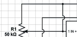
(Upper Left: Error Amplifier)
The Error Amplifier is connected to a potentiometer for testing purposes to vary the output voltage. It is fed a 2.5v reference (5v/2 from the REF pin)
(Lower Left: Frequency and Dead Time)
DTC is connected to ground for minimal dead time, since this is a single ended (as opposed to push/pull) there is no need for any higher dead time.
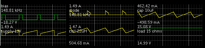
CT/RT form the timing circuit for 150kHz (148kHz actual)
(Upper Right: Error Amplifer and Reference)
While the schematic shows the second error amplifier as disconnected, it has been properly terminated to reference, and ground to prevent accidental trigger via noise. It has been omitted for clarity.
Reference is at 5v potential, it is divided to 2.5v for Error Amplifier #1.
Output control is grounded for single ended operation. (As opposed to push/pull)
(Lower Right: Switching Transistors and Output)
Please note that Vcc has been decoupled, and also has appropriate rail capacitance (0.1uF, and 1000uF respectively)
Input voltage is 19V, from a bench PSU
R5 connected to E2 for draining the MOSFET, and as a common collector switch.
SB330S is a 3A rated Shottky Diode, L1 is a 2A rated 22uH Inductor.
EDIT: I have found the problem. I switched to a logic level FET **broken link removed** from an IRF540.pdf but what would cause this problem? The max output voltage is now approximately 15v.
Greetings,
I have built a TL494 based buck converter, and have been having some trouble with it. In particular, I get about a 5v drop across the output when connected to a load. The maximum output voltage under load is about 13.4v. I need around 15v output, and no more than 1A for my application.
Circuit Schematic
I have done quite a bit of troubleshooting, and nobody can seem to figure out what is causing this. Below is a list of what I have tried to fix the issue.
- I have tested the input voltage drop, and peak current. There is no drop, and it is well within supply limit (5A bench PSU)
- I have connected the circuit to a 20, 10, and 3 ohm load and the supply regulates it perfectly without voltage drop (from the 13.4v)
- The output will go above 16v without a load (charging the output cap)
- The MOSFET gate is being fully switched on and off (Gate Waveform)
- I have also tried filtering the output with a low pass filter with the idea it may be producing higher voltage spikes.
Schematic Description:
(Upper Left: Error Amplifier)
The Error Amplifier is connected to a potentiometer for testing purposes to vary the output voltage. It is fed a 2.5v reference (5v/2 from the REF pin)
(Lower Left: Frequency and Dead Time)
DTC is connected to ground for minimal dead time, since this is a single ended (as opposed to push/pull) there is no need for any higher dead time.
CT/RT form the timing circuit for 150kHz (148kHz actual)
(Upper Right: Error Amplifer and Reference)
While the schematic shows the second error amplifier as disconnected, it has been properly terminated to reference, and ground to prevent accidental trigger via noise. It has been omitted for clarity.
Reference is at 5v potential, it is divided to 2.5v for Error Amplifier #1.
Output control is grounded for single ended operation. (As opposed to push/pull)
(Lower Right: Switching Transistors and Output)
Please note that Vcc has been decoupled, and also has appropriate rail capacitance (0.1uF, and 1000uF respectively)
Input voltage is 19V, from a bench PSU
R5 connected to E2 for draining the MOSFET, and as a common collector switch.
SB330S is a 3A rated Shottky Diode, L1 is a 2A rated 22uH Inductor.
Last edited: