Welcome to our site! EDAboard.com is an international Electronics Discussion Forum focused on EDA software, circuits, schematics, books, theory, papers, asic, pld, 8051, DSP, Network, RF, Analog Design, PCB, Service Manuals... and a whole lot more! To participate you need to register. Registration is free. Click here to register now.
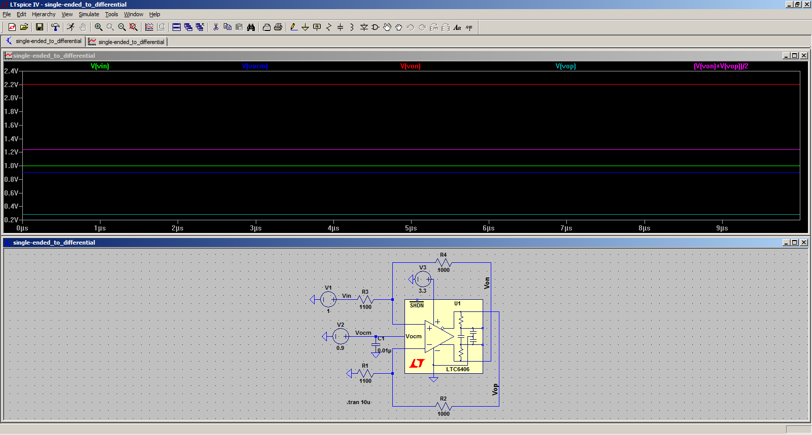
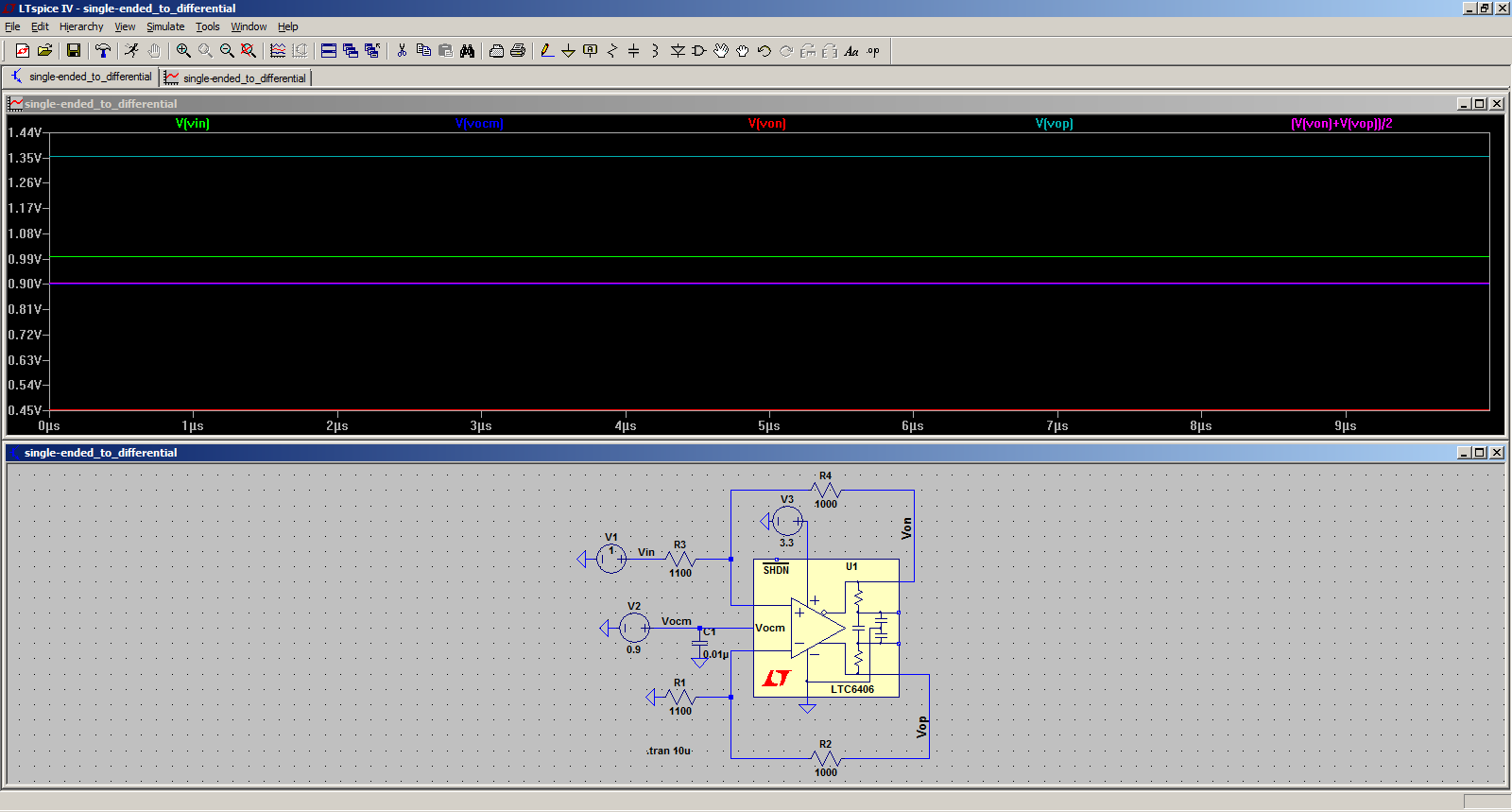
you've got the 'signal' ( V1 ) connected to the wrong input ?
Edit: oh yes... i think your outputs are also flipped in the symbol. Check your + & -, and also your Inverting (with the 'o' symbol) & non-Inverting (w/o the 'o') output points.
you've got the 'signal' ( V1 ) connected to the wrong input ?
Edit: oh yes... i think your outputs are also flipped in the symbol. Check your + & -, and also your Inverting (with the 'o' symbol) & non-Inverting (w/o the 'o') output points.
checkout this example setup from their website -- (rename file to .asc) View attachment 85997
This site uses cookies to help personalise content, tailor your experience and to keep you logged in if you register.
By continuing to use this site, you are consenting to our use of cookies.