Continue to Site

Welcome to EDAboard.com

Welcome to our site! EDAboard.com is an international Electronics Discussion Forum focused on EDA software, circuits, schematics, books, theory, papers, asic, pld, 8051, DSP, Network, RF, Analog Design, PCB, Service Manuals... and a whole lot more! To participate you need to register. Registration is free. Click here to register now.

[SOLVED] Help with LASER Diode Driver Circuit

Status
Not open for further replies.

devank.purohit

Newbie level 6
Joined
Dec 5, 2012
Messages
14
Helped
0
Reputation
0
Reaction score
0
Trophy points
1,281
Activity points
1,373
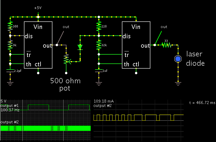
I wish to drive a LASER diode with the following input specifications:
1. A constant current of 50 - 120 mA
2. Forward voltage is 1.1 - 1.5V
The LASER diode has to be driven by a signal (MIX_OUT in the schematic attached) whose frequency is (9/11/15/18) KHz for the first 5 ms and 21 KHz for the next 5 ms. The problem is I have tried using a normal transistor configuration, darlington pair configuration but have been unable to achieve the desired results. Any help would be greatly appreciated.
 

Attachments

  • Test_Rx.png
    204.7 KB · Views: 87
Last edited by a moderator:

A 555 IC may be sufficient to provide up to 120 mA.

You would apply a particular volt level in the middle of the RC network, to alter the frequency.

Screenshot:


The scope traces show the output from each 555. The first one is adjusted to a frequency of 100 Hz.

The final frequency has just transitioned from 21 kHz to 9 kHz. (You may want to use one of the methods available for changing the duty cycle so it is closer to 50 percent.)
 

You have shown a large schematic but without any information about what you have tried for the laser circuitry ("... normal transistor configuration ..."?). Also, the laser specification is essential - has it a built in monitor photodiode, for example.

While it isn't your question, are you really going to use 7 microcontrollers for the project?

Keith
 

Have you considered current switching ? First from your Vcc, set up a constant current source down to the diode. This could just be a resistor if you do not want any special control of the current. ACROSS the transistor connect a NPN medium power transistor, feed its base from high gain emitter follower, connect base of this transistor to your source via a 500 ohm resistor. Now when the input signal goes high the laser diode goes off. I would have though a circuit like that was good for a couple of MHZ.
frank
 

Thank you all for your suggestions.
@Keith : No, actually. The design attached has been prepared by somebody else. I want to go for reduction of components as well. But before that, I wanted to make sure I am able to drive the circuit as per the requirements.
As for the laser diode, specifications are not available to us. All that is known is that it is a Russian equivalent of a certain IR LED Lamp (Datasheet attached).
 

Attachments

  • L1070.pdf
    801.6 KB · Views: 96

@ Brad: I had thought of using IC 555. But I felt that using a microcontroller would be better because of the digital outputs.

@ Frank: I tried the configuration which you have suggested. Problem is I am getting very high voltage spikes.
 

Switching spike are critical for laser diodes. A spike free current switch is best. The spike come inductance of the wiring. Protect the laser diode with a voltage limiting Z-diode and make the connection as short as possible. Another solution are the use integrated laser driver iC with spike free switching.

Enjoy your design work!
 

As for the laser diode, specifications are not available to us. All that is known is that it is a Russian equivalent of a certain IR LED Lamp (Datasheet attached).

So is it a laser or an LED? Lasers and LEDs are not interchangeable.

Keith
 

As of now, I am assuming that it is an IR LED Lamp with the aforementioned specifications.
 

Forward voltage is quite low so you should be able to simply drive it with a current limiting resistor. I would suggest a MOSFET makes the design easier, provided you choose something with a low threshold voltage so the PIC can turn it on fully. You should look for a reasonably low ON resistance, say below 1 ohm. You could get fairly small devices that can do that e.g. IRLML6346TRPBF has 1.1V maximum threshold and 80m ohm maximum resistance at 2.5V gate voltage in SOT23.

Keith
 

Thank you so much Keith.

I have a question though - The anode of the LED is connected to the ground and the signal needs to be given to the cathode. Will the aforementioned devices be capable of sinking that much current?
 

If the anode is connected to ground then you need a negative voltage on the cathode to drive it. Are you sure that the anode has to be grounded?

Keith
 

Oh yes. The anode is grounded. I was planning to use an inverting op amp followed by some current boosting circuit, after the microcontroller output. Will this work?
 

You can still use a simple NMOS driver but it needs to operate from you negative supply. You will then need to level shift your drive signal so it operates relative to the negative supply for driving the MOSFET.

Keith
 

On another note, how can I go about reduction in the number of microcontrollers?
 

On another note, how can I go about reduction in the number of microcontrollers?

It depends on if you need to run every frequency simultaneously or just one or two. If you only need one or two frequencies you simply use one microcontroller and switch the frequency in software. The PIC18F2550 has two PWM modules - there are PICs with more PWMs built in.

Keith.
 

Status
Not open for further replies.

Similar threads

Part and Inventory Search

Welcome to EDABoard.com

Sponsor

Back
Top