somegeek
Newbie level 3
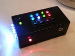
I built my kids a couple of 'control boxes', least that's what they call them. ") They have 4.8V 700mAh NiCd battery packs in them. The LEDs are wired with 100Ω resistors. I'd like to put a low voltage light on the box, a type of simple circuit that would shut power to the main circuit and switch to a 2nd circuit(with a single red LED for example) when the voltage drops below 4.4V or 4.0V? Some kind of feedback for them would be cool indicating it's time to charge. They're charging them with a trickle charger(4.8V@50mAh - old Futaba Rx charger). This way they can charge when they need and if they leave it plugged in past full, the pack won't be damaged.
They have 4.8V 700mAh NiCd battery packs in them. The LEDs are wired with 100Ω resistors. I'd like to put a low voltage light on the box, a type of simple circuit that would shut power to the main circuit and switch to a 2nd circuit(with a single red LED for example) when the voltage drops below 4.4V or 4.0V? Some kind of feedback for them would be cool indicating it's time to charge. They're charging them with a trickle charger(4.8V@50mAh - old Futaba Rx charger). This way they can charge when they need and if they leave it plugged in past full, the pack won't be damaged.
Appreciate any input.
somegeek
They have 4.8V 700mAh NiCd battery packs in them. The LEDs are wired with 100Ω resistors. I'd like to put a low voltage light on the box, a type of simple circuit that would shut power to the main circuit and switch to a 2nd circuit(with a single red LED for example) when the voltage drops below 4.4V or 4.0V? Some kind of feedback for them would be cool indicating it's time to charge. They're charging them with a trickle charger(4.8V@50mAh - old Futaba Rx charger). This way they can charge when they need and if they leave it plugged in past full, the pack won't be damaged.Appreciate any input.
somegeek