Continue to Site

Welcome to EDAboard.com

Welcome to our site! EDAboard.com is an international Electronics Discussion Forum focused on EDA software, circuits, schematics, books, theory, papers, asic, pld, 8051, DSP, Network, RF, Analog Design, PCB, Service Manuals... and a whole lot more! To participate you need to register. Registration is free. Click here to register now.

500 watt smps based inverter

Status
Not open for further replies.

--BawA--

Advanced Member level 1
Joined
Nov 28, 2012
Messages
479
Helped
43
Reputation
86
Reaction score
42
Trophy points
1,318
Location
Noida, INDIA
Activity points
4,926
hi
i have used 3+3 mosfet bank in my first stage of the inverter i.e dc to dc converter stage, so my question is how can protect my mosfets from burning? what protection circuit or components should i use along with the mosfets so that it does not burn in any case? i have made 3 times the mosfet banks but ,,after some time it get burned.....so please help me.....
 

what are you specifications of the inverter,and which of the side of mosfet get burnt?
 

configuration is 450 watts 12/220v ,,i have used pushpull topology for dc dc converter..
mosfet that i have used for driving the high frequency transformer got burned,,earlier that was working fine but yesterday it burned ,,i thing there is a problem in somthing else ,,so i want to know how to protect these mosfets from burning?
 

kabeer , can u please tell me ,,how this feedback works,,because as i dont know the working ,how can i handle it?
 

The feed back signal is used to control the duty cycle of the signal coming out from your oscillator and it is done by using a voltage divider at your final output then using a small variable resistor to to set your required output voltage this makes your output voltage stable even when you apply load the voltage remain the same,most of the pwm chips used for inverter uses this control to increase its efficiency.
 

Even without feedback, the MOSFETs shouldn't burn. That they do indicates that something's wrong (obviously, since the MOSFETs are burning).

The first reason I can think of is cross-conduction. I think you're using SG3525. SG3525 allows you to provide some dead-time to prevent cross-conduction. Make use of that feature. Connect a resistor between CT(pin 5) and DT (pin 7) of the SG3525. This resistor will determine the dead-time. Initially start with a resistance of 22Ω to 47Ω.

The second reason could be improper gate drive, causing excessive heating and then the MOSFETs to burn. Since you have 3 MOSFETs in parallel being driven at a frequency of 50kHz, I doubt the SG3525 on its own would be enough. Use a MOSFET driver at the output. If you can use a dedicated MOSFET driver such as the TC427, that's good. But even if you don't use a dedicated driver, at least use a totem-pole driver. You may go through this tutorial that I wrote: https://tahmidmc.blogspot.com/2012/12/low-side-mosfet-drive-circuits-and_23.html
Scroll down to Fig. 5 and Fig. 7.

The third reason could be spikes. For spikes on the drain, you should use snubber to suppress them.

Ensure that you have a gate to source resistor in place for each MOSFET.
Use a 4.7kΩ resistor from gate-to-source of each MOSFET.

Hope this helps.
Tahmid.
 
Of course we do. Thanks for pointing that out. :smile:

The voltage applied on the primary, number of windings and the core used (material, properties, area, etc) would determine whether the core saturates or not.
Besides that, mismatch between the 2 winding sections of the primary may also cause the core to saturate.

If the transformer saturates, the excessive current (in this case, the circuit is just a short circuit with the resistance of the transformer winding being the only resistance to the current) could cause the MOSFETs to burn.

The winding technique of the MOSFET could introduce (high) leakage inductances, thus introducing the "spikes" I previously mentioned. A snubber should thus be implemented.

There could be many other reasons. So, I think each point discussed should be checked and corrected (when required) by BawA one by one to identify the fault and correct it.

Hope this helps.
Tahmid.
 
thank u very much tahmid
i think my mosfet burnt due to core saturation, because 2days ago when i tested my circuit ,it was working fine ,but on the next day as i connected the wires to the battery my mosfets burnt at that instant only,,,,so plz tell me the significance of core saturation? some times there comes a noise from my transformer ,is it normal?
and also tell me about snubbers ? how they protect the mosfets from burning?
 

also tell my the configuration of the snubber thai i should use and how to connect snubber in the circuit?
 

Ensure that you have a gate to source resistor in place for each MOSFET.
Use a 4.7kΩ resistor from gate-to-source of each MOSFET.
please i also want to know the importance of that resistor between G and S.
Is it for discharging the charge of the gate to source capacitance? if so, why u select 4.7Kohm as we should decrease it to get faster discharge and faster MOSFET turn off ??

Regards,
Hz
 

thank u very much tahmid
i think my mosfet burnt due to core saturation, because 2days ago when i tested my circuit ,it was working fine ,but on the next day as i connected the wires to the battery my mosfets burnt at that instant only,,,,so plz tell me the significance of core saturation? some times there comes a noise from my transformer ,is it normal?
and also tell me about snubbers ? how they protect the mosfets from burning?

If the transformer saturates, it basically is just a piece of wire with zero (near-zero) inductance. So, when the MOSFET is on, there is a short-circuit and excessive current causes the MOSFET to burn.

To figure out whether a transformer saturates or not, you need to know about the voltage applied to the primary, the number of turns on the primary, the transformer effective core area and the flux density.

Please go through this for winding transformers and figuring out whether the transformer has saturated due to excess flux density:

https://tahmidmc.blogspot.com/2012/12/ferrite-transformer-turns-calculation.html

The transformer can also saturate due to mismatch in the 2 primary windings or the 2 primary drive signals.

Make sure that you have a 0.1uF capacitor connected between SG3525 pin 9 and ground.

Hope this helps.
Tahmid.

- - - Updated - - -

please i also want to know the importance of that resistor between G and S.
Is it for discharging the charge of the gate to source capacitance? if so, why u select 4.7Kohm as we should decrease it to get faster discharge and faster MOSFET turn off ??

Regards,
Hz

It is to prevent accidental turn-on of the MOSFET.

We don't select too low as it increases current drive requirement of the driver. Here, I mentioned 4.7k for each MOSFET. Since there are 3 MOSFETs in each combination, the combined gate-to-source resistance will be 4.7k/3 = 1.57k. If we use 12V to drive the MOSFETs, the current draw by the combined resistance will be 7.64mA.

Hope this helps.
Tahmid.
 

Tahmid how to select snubber ..and how to connect it in the circuit??
 

tahmid
do i have to make inductor by my own or it is available in the market? if i hve to build an an inductor for dc stage filter and for output low pass filter ,then how should i select the core for it?
 

You may be able to find inductors in the market, but you can also easily wind them yourself by obtaining proper cores and wires. Select a core that is large enough to handle a lot of turns with a thick enough core. You should be able to easily use cores > 2cm in diameter.

Connect a snubber across the primary of the transformer. You may (or may not) need to use snubbers across the MOSFETs.

Hope this helps.
Tahmid.
 
thanx tahmid
1) are u talking about torroidal core of diameter >2cm or a linear core? does this core is having any no. like for transformer we hve used ETD44,,does this also have any no,
2) how to choose snubber,,i mean what should i say to shopkeper,,just to give a snubber,,is it not having any configuration?

1) I was talking about toroid core. Yes, the cores have numbers. You should go to the market and see which are available.

2) Snubber is a combination of resistor, capacitor and diode. In this case, when snubber is used across transformer, you can use 2 RCD snubbers across the 2 primaries or a single RC snubber across the primary (omitting the center tap). So, you need to make the snubber yourself. Before going on to design snubbers, you should read up on snubbers.

Hope this helps.
Tahmid.
 
tahmid
i hve tried to read snubbers on net ,but that seemed very hard ,,many abbreviations have been used there ,so i could not understand,so this is my request that u please tell me in detail how to calculate the value of R and C in RC snubbers, till now i have burnt 18 mosfets,,so this time i don't want to do the same thing happen again,,so please help me ,,,
 

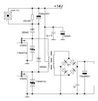
Hi. I usually use such scheme -
Also it is necessary to pay attention on sufficient capacity of capacitors in feeding chains.
now i have burnt 18 mosfets
but what type of fets exactly used?
 
Last edited:

thanx deepone
i have used irfz44n and irfz48n
can u please explain the circuit?
as tahmid has said that snubber will be used between drain and transformer,i m not able to find that in ur circuit ,please explain //
 

Status
Not open for further replies.

Similar threads

Part and Inventory Search

Welcome to EDABoard.com

Sponsor

Back
Top