Continue to Site

Welcome to EDAboard.com

Welcome to our site! EDAboard.com is an international Electronics Discussion Forum focused on EDA software, circuits, schematics, books, theory, papers, asic, pld, 8051, DSP, Network, RF, Analog Design, PCB, Service Manuals... and a whole lot more! To participate you need to register. Registration is free. Click here to register now.

[SOLVED] Problem with my DIY Pickit2

Status
Not open for further replies.

Plateau

Junior Member level 3
Joined
Jan 4, 2012
Messages
30
Helped
2
Reputation
4
Reaction score
2
Trophy points
1,288
Activity points
1,553
Hello, folks, are you all ok?

I'm facing a problem with my DIY Pickit 2 clone made by me. I've followed the steps from these references:

Website
Reference 2

...and I've made some changes in layout (I put the most part of resistor in vertical position and added an external power supply for debugging).

After solving some problems with the bootloader, now the problem is about VDD voltage level. When I connect the USB cable on the board, the Pickit2 is recognized by PC but the Pickit2 Software 2.61v always shows me this message: Pickit2 VDD voltage level error. Check target and retry operation.

If I plug the external power supply on, the VDD voltage level error stops and the Pickit2 works perfectly.

Well, I wouldn't like to use the external power supply all the time.

Could anybody help me?

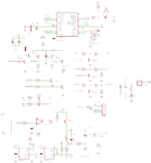
Schematic
schematic.png

Board

board.png
 

Hello, lijoppans, how are you?

The modified schematics are in my first post. My PCB was created by modifying this Reference for using "normal" electronic parts (not SMD).

Well... I'll take a look on the reference gave by you.

Thanks in advance,

Pedro Rosa.
 

Hi,

Looks like you have built a very close copy of the full Pk2, whereas most diy versions are a lot simpler without the eeproms etc.

You say the Pk2 works fine on an external psu , but you do not say what is connected to the Pk2, just a chip to be programmed or to a full circuit board ?

As I am sure you know, you must have the correct circuitry on your board if its to be used for ICSP.

Also assume you are using Pk2 V2.61 program rather than direct from MPlab.

Have you gone into the Tools, Troubleshooting section and run those tests ?

I would first get the Pk2 working using V2.61 with just a Pic chip connected directly to it with no external circuitry or psu and get that sorted out properly.

To me it sounds like you have a fault in either the pk2 +5v rails or something on your external board, which just using a pic chip shoulsd soon eliminate.
 

Please show me the modified schematics....2.............

I made a Pickit2 clone...... It can't program 3.3V devices


Hi,

Yes you can, I made a pk2 with a fixed 5v rail like yours.

You can do it two ways.

1. Apply 3v3 to the target chip /circuit before you power on the PK2, with the circuit like yours it will sense the 3v3 on the chip and turn off the +5v.
( just make sure Pk2 Vdd target is switched off)

2. The safer way I prefer, is to fit a 3v3 regulator on the +5v rail where the usb connector comes in so the whole PK2 circuitry is run on 3v3.
( I use the standard pic18F2550, not the LF version, and its programmed 18LF and Pic24 chips at 3v3 without problems.
 
Hello, folks, are you al ok?

First of all, merry christmas!!!

I got mad due to the last problem and so I decided to make another PCB using all the files from the first reference (https://www.circuitvalley.com/2011/...howComment=1356263781754#c1820552152028921641).

My PCB seems ok, but now I'm facing another problem (well... I'm thinking I'm not lucky. haha).

The problem is:

When I plug the USB cable, the board is recognized but when I open the Pickit 2 Software 2.61v it gives me a VPP voltage level error (as you can see below)

**broken link removed**

If I go ahead through Troubleshooting, the first stage goes ok (VDD test, as you can see below).


But in VPP test, the Troubleshooting gives me this error:


In the last test (PGD and PGC) everything goes ok.

Well... I dont know what can I do. I realized a strange fact: if I remove the 47µF capacitor, this error (VPP Short circuit) does not happen, but the VPP voltage is too crazy (sometimes is 13v, sometimes is 2v). The voltage through BAT54 diode is 12.2 volts when I make VPP test. Thus, I think the "DC-DC converter" is ok.

Tomorrow I will try to replace all transistors (2N3904 and 2N3906), except BD140 and I hope this problem can be solved.

If somebody has any idea, feel free for helping me. haha

Thanks in advance, folks.


Hi,

Its interesting that you do not have the +5v error on this build, though are your tests done with anything connected to the Pk2 ?

One of the first things the Pk2 software does is check the +5v and +12v lines and gives an error if things are not right.

You may have your transistors the wrong way round, its important you verify the pinout for the ones you bought, they can, but not often, vary in pinout from one manufacturer to another.

The 47uf is an integral part of the charge pump at it will not work without it.

No mention of a BAT54 in that link you show ? - assume its used instead of T2 ?
Have you substituted any other parts ?

If you are getting a proper 12v on your meter during the vpp test then perhaps look at the vpp feedback line r10/r11, thats what the program uses to detect is vpp is ok
 
Hiho, wp100, are you ok?

I'll answer these questions using the quote tool to simplify.

Its interesting that you do not have the +5v error on this build, though are your tests done with anything connected to the Pk2 ?

All my tests I've done without any device connected to the Pk2.

You may have your transistors the wrong way round, its important you verify the pinout for the ones you bought, they can, but not often, vary in pinout from one manufacturer to another.

I realized in this SCH there are 3 transistors placed mirrored on the PCB. Please, take a look in Q4 , Q6 (both 2N3906) and T5 (2N3904). Yesterday, I replaced all of these transistors and I put others removed from electronic scrap. Today I've bought a new parts and I'm going to replace them later.

The 47uf is an integral part of the charge pump at it will not work without it.

Huuuuum. The mistery is why Pk2 does not detect Short Circuit when I remove this capacitor. Too crazy haha.

No mention of a BAT54 in that link you show ? - assume its used instead of T2 ?
Have you substituted any other parts ?

I've found some BAT46 and BAT54 at home and so, I've replaced T2 for security. Furthermore, I replaced a 2N3904 to BC548 (respecting the pinout) and a 2N3906 to BC557 (respecting the pinout)... but today later I'll replace all transistors for new parts.

If you are getting a proper 12v on your meter during the vpp test then perhaps look at the vpp feedback line r10/r11, thats what the program uses to detect is vpp is ok

On the BAT54 cathode there is 12.2v and vpp feedback line there is 4.44v. Maybe this value can be higher than necessary but I think it's correct.

One more time thank you so much, wp100.

Best regards,

Pedro Rosa.
 
Last edited:

Hi,

Sound like the classic build problem, replacing so many parts you begin to wonder which are good and which are bad.

You can often get a chain reaction where one part damages the next and so on.

Although making a new pcb seems the right way, its often worth using all new parts to eliminate anything suspect.

Using substitute parts you must be sure they are suitable. You are using a 680 or 470uh choke ?


The project you show looks a very thorough presentation so have little reason to doubt that its a good proven design.

However its almost a full copy of the Pk2, and its often said you might find it quicker and cheaper to buy a Pk2 or Pk3 than trying to build your own.

Many PK2 designs shown in the forum are much simpler 4 transistor versions.

Perhaps you might be better trying one of those ?

Below is my diagram which works fine, though I hand wired it, but if you search this forum you will find similar designs with a circuit board layout.
I built it as back for my purchased Microchip Pk2
 

Attachments

  • pk2hi.jpg
    808.6 KB · Views: 129
Hi,

Sound like the classic build problem, replacing so many parts you begin to wonder which are good and which are bad.

You can often get a chain reaction where one part damages the next and so on.

Although making a new pcb seems the right way, its often worth using all new parts to eliminate anything suspect.

Using substitute parts you must be sure they are suitable. You are using a 680 or 470uh choke ?


The project you show looks a very thorough presentation so have little reason to doubt that its a good proven design.

However its almost a full copy of the Pk2, and its often said you might find it quicker and cheaper to buy a Pk2 or Pk3 than trying to build your own.

Many PK2 designs shown in the forum are much simpler 4 transistor versions.

Perhaps you might be better trying one of those ?

Below is my diagram which works fine, though I hand wired it, but if you search this forum you will find similar designs with a circuit board layout.
I built it as back for my purchased Microchip Pk2

Hiho, wp100, are you ok?

Thank you so much for helping me.

I'm making this Pk2 because here in Brazil it is a little bit expensive and I need to program some 3.3v PICs.

Could you think whether I change all transistors and choke, everything is going to be ok? By the way, at the first moment I've used a 1.5mH inductor (the first PCB who only works with external power supply) but I've found a 660uH and 1mH at home.

Another strange fact is when I use the 1mH or 1.5mH inductor a little noise is produced by inductor during VPP test but nothing happen with the 660uH inductor.

Well, thanks again.

Regards.
 

Hi,

If you get 12v then assume those higher value chokes must work ok.

As mentioned in entry #6 you can program some 3v chips even with that very basic design.

You do not say exactly which chips you are wanting to program - assume you have checked they can be programmed by the Pk2, many of the newer chips cannot.
Also worth checking they can be debugged by Mplab /Pk2

The Pk3 is becoming the main programmer now and the few Pk2 clones that were sold as ready made units have dropped in price.

This one from Sure is around USD $16 delivered + any local import taxes which seems a really good price and Sure have always given me good service.

**broken link removed**

Hello, wp100, how are you?

I'm coming back here to tell you I finally found the solution. :grin:

After replace all transistors (except BD140) and some resistances and none result, I've found a short circuit on the PCB (originated when I used a pen to fix an error during the toner transfer). I only scraped the short circuit and everything worked out.

Now, I can program my PICs and go ahead with my project. I don't know how to express my thankfulness but thank you so much for having helped me and for the patience.

Best regards,

Pedro Rosa.
 

Hi,

Good to hear you got it working ok.

So thats the easy part done :lol: - what kind of program / project are you thinking of making ?
 

Hi,

Good to hear you got it working ok.

So thats the easy part done :lol: - what kind of program / project are you thinking of making ?

I'm making a vehicle track system using a GPS, GSM module (Fastrax UP501 and SIMCom SIM900D, respectively) controlled by a PIC 18F4680. When I finish the project I'll put here.

One more time thank you so much.

Regards,

Pedro Rosa.
 

I'm making a vehicle track system using a GPS, GSM module (Fastrax UP501 and SIMCom SIM900D, respectively) controlled by a PIC 18F4680.


Hi,

Well thats a co-incidence ! I have just been doing something very similar with my 18F4520, or at least trying to.

I had looked at the Sim900 and similar modules but they cost over GB £70.

One of these units seemed to offer all I needed as its just to send out a simple sms alarm from a static location.
**broken link removed**

Though clearly brand new, it was sadly dead on arrival, have just posted it back to China, though it will be at least 4 weeks before I get anything back.
 

Attachments

  • $(KGrHqNHJDcFBtwD8,b1BQm83VM)Rg~~60_12.JPG
    $(KGrHqNHJDcFBtwD8,b1BQm83VM)Rg~~60_12.JPG
    3.1 KB · Views: 159

Hi,

Well thats a co-incidence ! I have just been doing something very similar with my 18F4520, or at least trying to.

I had looked at the Sim900 and similar modules but they cost over GB £70.

One of these units seemed to offer all I needed as its just to send out a simple sms alarm from a static location.
**broken link removed**

Though clearly brand new, it was sadly dead on arrival, have just posted it back to China, though it will be at least 4 weeks before I get anything back.

Huuum, 70 GBP is too much expensive. Do you know how much does the SIM900 chip cost? I've bought a SIM900 for US$20 in China and a SIM900D for US$45 here in Brazil. If you can make your own PCB it's a good choice for you.

Well, if you need some information about feel free for asking me.

Regards. :D
 

Status
Not open for further replies.

Similar threads

Part and Inventory Search

Welcome to EDABoard.com

Sponsor

Back
Top