Continue to Site

Welcome to EDAboard.com

Welcome to our site! EDAboard.com is an international Electronics Discussion Forum focused on EDA software, circuits, schematics, books, theory, papers, asic, pld, 8051, DSP, Network, RF, Analog Design, PCB, Service Manuals... and a whole lot more! To participate you need to register. Registration is free. Click here to register now.

How to set Proteus 7 Segment Refresh rate with PIC 16F628A

Status
Not open for further replies.

asking

Full Member level 5
Joined
Sep 21, 2010
Messages
279
Helped
6
Reputation
12
Reaction score
6
Trophy points
1,298
Activity points
3,377
Hello,

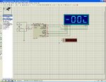
i m trying to build one counter circuit with 4 7-Segment multiplexing... my program is correct but still not properly working with proteus simulation...so guyz.. i need to calculate how to calculate refresh rate "Minimum Trigger" setting in 7 segment display properties....should i keep it default or some calculation is required ?

i have attached the image...i have kept 5ms refresh rate for display but still proteus is not showing proper...data..on display....please help...

MikroC Code:
Code:
unsigned short i, DD0, DD1, DD2, DD3;
unsigned int Count;
//------ Function to Return mask for common anode 7-seg. display
unsigned short mask(unsigned short num) {
 switch (num) {
  case 0 : return 0x3F;
  case 1 : return 0x06;
  case 2 : return 0x5B;
  case 3 : return 0x4F;
  case 4 : return 0x66;
  case 5 : return 0x6D;
  case 6 : return 0x7D;
  case 7 : return 0x07;
  case 8 : return 0x7F;
  case 9 : return 0x6F;
 } //case end
}
void main() {
  CMCON  |= 7;        // Disable Comparators
  TRISB = 0x00; // Set PORTB direction to be output
  PORTB = 0xff;    // Turn OFF LEDs on PORTB
  TRISA = 0b00100000; // RA5 is input only
  Count   =    0;  // Initial Value of Counter

  do {
  DD0 = Count%10;  // Extract Ones Digit
  DD0 = mask(DD0);
  DD1 = (Count/10)%10; // Extract Tens Digit
  DD1 = mask(DD1);
  DD2 = (Count/100)%10; // Extract Hundreds Digit
  DD2 = mask(DD2);
  DD3 = (Count/1000);  // Extract Thousands Digit
  DD3 = mask(DD3);

  for (i = 0; i<=50; i++) {
      PORTB = DD0;
      RA0_bit = 0;      // Select Ones Digit
      RA1_bit = 1;
      RA2_bit = 1;
      RA3_bit = 1;
      delay_ms(5);
      PORTB = DD1;
      RA0_bit = 1;
      RA1_bit = 0;     // Select Tens Digit
      RA2_bit = 1;
      RA3_bit = 1;
      delay_ms(5);
      PORTB = DD2;
      RA0_bit = 1;
      RA1_bit = 1;
      RA2_bit = 0;     // Select Hundreds Digit
      RA3_bit = 1;
      delay_ms(5);
      PORTB   = DD3;
      RA0_bit = 1;
      RA1_bit = 1;
      RA2_bit = 1;
      RA3_bit = 0;     // Select Thousands Digit
      delay_ms(5);
      }
      Count = Count + 1 ;
      if (Count > 9999) Count = 0;
  } while(1);          // endless loop
}
 

Attachments

  • 7 segment multiplexing simulation error.JPG
    7 segment multiplexing simulation error.JPG
    255.1 KB · Views: 164
Last edited:

Code:
unsigned short i, DD0, DD1, DD2, DD3;
unsigned int Count;
//------ Function to Return mask for common anode 7-seg. display
unsigned short mask(unsigned short num) {
 switch (num) {
  case 0 : return 0x3F;
  case 1 : return 0x06;
  case 2 : return 0x5B;
  case 3 : return 0x4F;
  case 4 : return 0x66;
  case 5 : return 0x6D;
  case 6 : return 0x7D;
  case 7 : return 0x07;
  case 8 : return 0x7F;
  case 9 : return 0x6F;
 } //case end
}
void main() {
  CMCON  |= 7;        // Disable Comparators
  TRISB = 0x00; // Set PORTB direction to be output
  PORTB = 0xff;    // Turn OFF LEDs on PORTB
  TRISA = 0b00100000; // RA5 is input only
  Count   =    0;  // Initial Value of Counter

  do {
  DD0 = Count%10;  // Extract Ones Digit
  DD0 = mask(DD0);
  DD1 = (Count/10)%10; // Extract Tens Digit
  DD1 = mask(DD1);
  DD2 = (Count/100)%10; // Extract Hundreds Digit
  DD2 = mask(DD2);
  DD3 = (Count/1000);  // Extract Thousands Digit
  DD3 = mask(DD3);

  for (i = 0; i<=50; i++) {
  
  
      RA3_bit = 1;		//disable RA3
      PORTB = DD0;
      RA0_bit = 0;      // Select Ones Digit
      RA1_bit = 1;
      RA2_bit = 1;
      delay_ms(5);
	  
      RA0_bit = 1;		//disable RA0
      PORTB = DD1;
      RA1_bit = 0;     // Select Tens Digit
      RA2_bit = 1;
      RA3_bit = 1;
      delay_ms(5);
	  
      RA1_bit = 1;		//disable RA1
      PORTB = DD2;
      RA0_bit = 1;
      RA2_bit = 0;     // Select Hundreds Digit
      RA3_bit = 1;
      delay_ms(5);
	  
      RA2_bit = 1;		//disable RA2
      PORTB   = DD3;
      RA0_bit = 1;
      RA1_bit = 1;
      RA3_bit = 0;     // Select Thousands Digit
      delay_ms(5);
      }
      Count = Count + 1 ;
      if (Count > 9999) Count = 0;
  } while(1);          // endless loop
}
Image00000.jpg
 
  • Like
Reactions: asking

    asking

    Points: 2
    Helpful Answer Positive Rating
thanks...but i did not noticed any changes in program and also how you connected that display with those arrows ? i m not able to find that.......
 

These are different.
001.jpg
Code:
/*********************************************************** 
Part of old code
***********************************************************/ 
//for example DD0=0x7D display="6",DD1=0x4F display="3"
PORTB = DD0;//DD0=0x7D
RA0_bit = 0;// Select Ones Digit, display X X X 6
RA1_bit = 1;//display X X X 6
RA2_bit = 1;//display X X X 6
RA3_bit = 1;//display X X X 6
delay_ms(5);//hold
PORTB = DD1;//DD1=0x4F,becasue RA0_bit=0,[COLOR="#FF0000"]display X X X 3,this is the wrong results![/COLOR]
RA0_bit = 1;//display X X X X
RA1_bit = 0;//Select Tens Digit,display X X 3 X
RA2_bit = 1;
RA3_bit = 1;
delay_ms(5);
PORTB = DD2;
RA0_bit = 1;
RA1_bit = 1;
RA2_bit = 0;// Select Hundreds Digit
RA3_bit = 1;
delay_ms(5);
PORTB   = DD3;
RA0_bit = 1;
RA1_bit = 1;
RA2_bit = 1;
RA3_bit = 0;// Select Thousands Digit
delay_ms(5);
/*********************************************************** 
Part of new code
***********************************************************/ 
//for example DD0=0x7D display="6",DD1=0x4F display="3"
RA3_bit = 1;//disable RA3,display X X X X
PORTB = DD0;//DD0=0x7D
RA0_bit = 0;// Select Ones Digit,display X X X 6
RA1_bit = 1;//display X X X 6
RA2_bit = 1;//display X X X 6
delay_ms(5);//hold
RA0_bit = 1;//disable RA0,display X X X X
PORTB = DD1;//DD1=0X4F
RA1_bit = 0;// Select Tens Digit,display X X 3 X
RA2_bit = 1;
RA3_bit = 1;
delay_ms(5);
RA1_bit = 1;//disable RA1
PORTB = DD2;
RA0_bit = 1;
RA2_bit = 0;// Select Hundreds Digit
RA3_bit = 1;
delay_ms(5);
RA2_bit = 1;//disable RA2
PORTB   = DD3;
RA0_bit = 1;
RA1_bit = 1;
RA3_bit = 0;// Select Thousands Digit
delay_ms(5);

- - - Updated - - -

The circuit of the same wire label is connected.Reference ISIS help“wire label”.

003.jpg
 
Last edited:
  • Like
Reactions: asking

    asking

    Points: 2
    Helpful Answer Positive Rating
thanks aton :) for information..
 

Status
Not open for further replies.

Similar threads

Part and Inventory Search

Welcome to EDABoard.com

Sponsor

Back
Top