Vermes
Advanced Member level 4
Pull-up and pull-down resistor is a common mechanism used in basic electronic circuits. Pull-up means connection of a line or chip, with supply voltage though a resistor with a value of few kOhms. This kind of connection results in maintaining high state, when the external devices are disconnected or do not give signals, and protects against unknown states. Pull-down resistors operate in an analogous manner. A pull-up resistor is a resistor connecting an input to VCC, and on the other side - a pull-down resistor is used for the connection of an input and GND. As it is called, it pulls the signal to high (pull-up resistor) or low state (pull-down resistor), and of course, it also limits the current.
The input state of most logic gates is a high impedance state, therefore it has no power of its own. Depending on this, when nothing is connected to it, the state floats depends on noises.
The two examples which are presented below describe the need of pull-up and pull-down resistor mechanism.
The picture shows a gate/microchip input which is connected to the ground using a switch. As you can see, the low state is done by closing the switch. But, if you open the switch, the input state is unknown, its floats depend on interferences from other power lines etc.
Let us learn how to set the input to a high state.
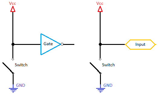
You have now a Vcc connection - when the switch is open, the input is in a high state. To get the input to a low state, theoretically you should close the switch. But you mustn't do that! When you close the switch, you short Vcc to GND, which could damage your power supply or other parts of your device. Depending on well-known Ohm's law, which says that: R = U/I when the R is 0, the current goes to infinity. To avoid this, you should use described here in this article pull-up resistor, which is shown in the picture below.
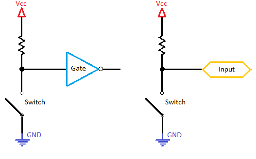
10 to 100k Ohms resistors are mainly used as pull-up/pull-down resistors. Let's look at the circuit now (let's assume that this resistor is 10kOhms). When the switch is connected, Vcc is shorted to GND, but in the middle of it, there is a 10kOhm resistor, which (depending on the Ohm's law) limits the current according to the formula: I=U/10kOhms. On microchips, the voltage is mainly equal 5 or 3.3V, therefore the current is 0.5mA or 0.33mA, but pull-up/pull-down resistors are also used with other voltages, for example to drive a FET with 12V. You should always remember that there is no need of high current because this kind of inputs depends on voltage.
Let's look now at an example with a pull-down resistor.
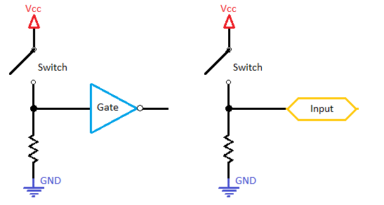
Although, this solution is rather rarely used, because of the fact that it solves the problem partially. When the switch is closed, Vcc isn't shorted to GND, but the Vcc is shorted to the input which will force the input to have an internal limiting resistor. Without that you could even damage it.
Below, you can see some practical usages of pull-down and pull-up resistors.
Optocouplers need pull-up resistors
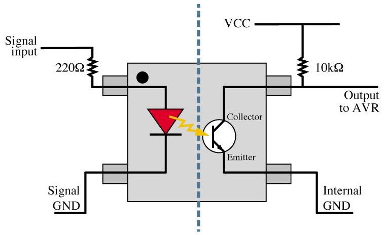
As you can see on the right side, a 10k pull-up resistor is used in this case. Without this pull-up resistor, the input (in the case when the diode isn't lighting) would have an unknown -floating state.
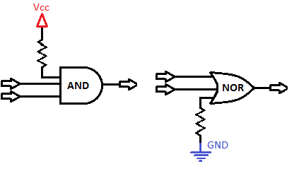
Gates with pull-up and pull-down resistors
AND/NAND gates could use a pull-up resistor in order to get a logical 1, and OR/NOR gates use a pull-down resistor to get a logical 0. Without the resistors, the gates could possibly be damaged (if the input was connected to VCC)!
The input state of most logic gates is a high impedance state, therefore it has no power of its own. Depending on this, when nothing is connected to it, the state floats depends on noises.
The two examples which are presented below describe the need of pull-up and pull-down resistor mechanism.
The picture shows a gate/microchip input which is connected to the ground using a switch. As you can see, the low state is done by closing the switch. But, if you open the switch, the input state is unknown, its floats depend on interferences from other power lines etc.
Let us learn how to set the input to a high state.
You have now a Vcc connection - when the switch is open, the input is in a high state. To get the input to a low state, theoretically you should close the switch. But you mustn't do that! When you close the switch, you short Vcc to GND, which could damage your power supply or other parts of your device. Depending on well-known Ohm's law, which says that: R = U/I when the R is 0, the current goes to infinity. To avoid this, you should use described here in this article pull-up resistor, which is shown in the picture below.
10 to 100k Ohms resistors are mainly used as pull-up/pull-down resistors. Let's look at the circuit now (let's assume that this resistor is 10kOhms). When the switch is connected, Vcc is shorted to GND, but in the middle of it, there is a 10kOhm resistor, which (depending on the Ohm's law) limits the current according to the formula: I=U/10kOhms. On microchips, the voltage is mainly equal 5 or 3.3V, therefore the current is 0.5mA or 0.33mA, but pull-up/pull-down resistors are also used with other voltages, for example to drive a FET with 12V. You should always remember that there is no need of high current because this kind of inputs depends on voltage.
Let's look now at an example with a pull-down resistor.
Although, this solution is rather rarely used, because of the fact that it solves the problem partially. When the switch is closed, Vcc isn't shorted to GND, but the Vcc is shorted to the input which will force the input to have an internal limiting resistor. Without that you could even damage it.
Below, you can see some practical usages of pull-down and pull-up resistors.
Optocouplers need pull-up resistors
As you can see on the right side, a 10k pull-up resistor is used in this case. Without this pull-up resistor, the input (in the case when the diode isn't lighting) would have an unknown -floating state.
Gates with pull-up and pull-down resistors
AND/NAND gates could use a pull-up resistor in order to get a logical 1, and OR/NOR gates use a pull-down resistor to get a logical 0. Without the resistors, the gates could possibly be damaged (if the input was connected to VCC)!