mr_monster
Member level 4
I would like to make a simulated inductor which is tune-able using an opamp implementation of an opamp. I could find a good source for the design process so anything like that would be greatly appreciated. Thanks!
Follow along with the video below to see how to install our site as a web app on your home screen.
Note: This feature may not be available in some browsers.
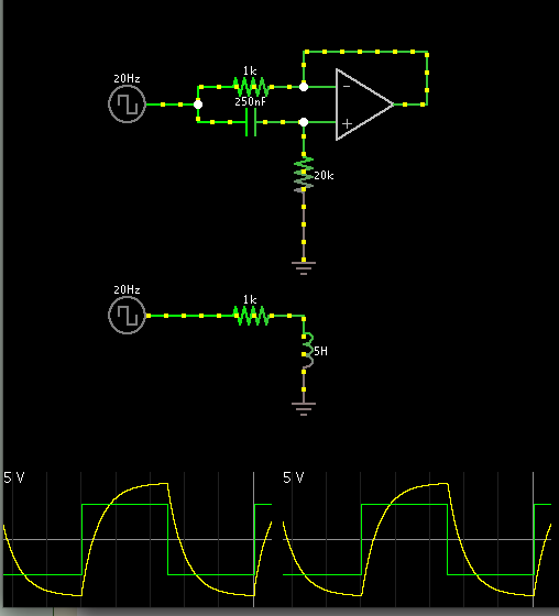
Falstad's animated simulator includes a gyrator (active inductor) in its menu of circuits.
Screenshot:
Clicking this link will open the falstad.com website, load the above schematic, and run it on your computer. (Click Allow to load the Java applet.)
https://tinyurl.com/axjyjqz
You can change values by right-clicking a component and choosing Edit.
I don't know how to make it tunable.
I would like to make a simulated inductor which is tune-able using an opamp implementation of an opamp. I could find a good source for the design process so anything like that would be greatly appreciated. Thanks!
As you will have noted - the circuit as given in post#2 is an active lossy inductor.
In case you need a lossless inductor you must use a GIC implementation using two opamps.
When you say lossless, you mean without series resistance? What would be a Q of such an inductor if that is even discussable in those terms? What about the Q of a simulated inductor? reactance / resistance?
I can make a tunable version by using a variable resistor instead of resistor going to ground?
I would like to make a simulated inductor which is tune-able using an opamp implementation of an opamp. I could find a good source for the design process so anything like that would be greatly appreciated. Thanks!
Sure I would like to see that!