Continue to Site

Welcome to EDAboard.com

Welcome to our site! EDAboard.com is an international Electronics Discussion Forum focused on EDA software, circuits, schematics, books, theory, papers, asic, pld, 8051, DSP, Network, RF, Analog Design, PCB, Service Manuals... and a whole lot more! To participate you need to register. Registration is free. Click here to register now.

[SOLVED] TEK TDS320 ch2 trace is off 2 minutes after POWER is ON

Status
Not open for further replies.

jalves_pt

Junior Member level 1
Joined
Nov 11, 2012
Messages
15
Helped
0
Reputation
0
Reaction score
0
Trophy points
1,281
Activity points
1,460
Hello,

New here but in need of your help.

I bought a used Tek TDS320 to play with (brand "new" , no errors in the scope log), I was using dual trace to see a video signal with 1 byte coded in line 10 in order to program an arduino to do video telemetry.
And had ch2 to check for the output of a lm393 (preparing the pulses to be read by arduino).

All the sudden the trace of ch2 become unstable and move up in the display till it disappear.

Now, If I turn off the scope for several hours, when I power up the scope I have both traces, but after aprox. 2 minutes, the ch2 trace oscillates and move up in the Tek display till it disappear.

I have no clue why this is happening, if it was something broke, it won't work for two minutes, it lead me to think that its heat related, but what???

What can I do to find the problem??

Thanks.
 

Yes, it sounds as though something goes wrong as a component heats up. This may provide a way for you to locate the faulty component.

The likely problem areas are the vertical deflection circuitry, or the high voltage circuitry.

Question:

1. Does the beam continue to sweep from left to right, as it moves upward?

2. Does the trace stay the same brightness as it moves upward? Or does it go dim?

3. Can you open up the housing and locate any burned looking component?

There is a chilling aerosol spray which you can spray on components, in the hopes of cooling the bad one and temporarily restoring operation. Then you can focus on that area.
 

Thank yo for your reply.

1. It seems so, the scope is a digital one and the trace goes up with little disruption if any. CH1 trace stays untouched although it seems perhaps more noisy.

2. It seems to maintain the brightness as it goes up.

3. Yes, I did and check the boards for bad capacitors. The smd ones has very good looks (as new) and the electrolytic looks also very good. There is no traces of corrosion any where I could see . The only board I didn't inspect was the frontal board, incidently or not the button "Waveform OFF" doesn't work, it won't remove the trace selected from the display. All the other buttons work well.
 

Does "Waveform OFF" make a beam disappear and re-appear? Then that circuit is a prime suspect.

I can't be sure, but I don't think it simply disconnects the high voltage wire. That would run into trouble.

Suppose the "Waveform OFF" button activates a component which pulls a wire low or high, rather than disconnect something. And suppose it is made to operate quickly. Normally you would see the beam disappear immediately and come back immediately (more or less).

However now suppose the component is no longer acting as a digital device (reliably on or off), but responds to internal heating effects (again I don't know for sure)? So could it be that the beam is normal for a while after power-up (while the component is cool), but then gets unreliable as the component heats up?

And this would be speculation, but suppose the beam is designed to be parked at the top of the scope, unseen, when the waveform is Off? Then it moves gradually upward. And suppose the button is stuck in one position (closed, maybe), causing continual current in the component that is designed to move the beam up and down?

However for all I know, the horizontal sweep is simply turned Off when the 'waveform Off' button is pressed.

Nevertheless, try touching components in the vicinity of the 'waveform OFF' switch. See if any components get too hot to touch as the unit warms up. Particularly transistors.

If you don't have cooling spray then it might work to put a drop of water on top of a component.

Consider disconnecting the 'waveform OFF' switch, on the chance it will bring the beam back onscreen.
 

I miss your post by very little.

I open the scope and disassembled the frontal panel, found two smd electrolytic 33uF caps. One had the terminal solder joint corroded, the other look all right.

Some electrolytic fluid was visible in the area of the "waveform off" button (in the other side of the pcb, which I thought was odd) so I decide to replace both caps. Only have through hole 33yF 16V caps, so that was what I use.

I recover the action of the "Waveform off" button, it is working again, but unfortunately, the trace of the CH2 continues to go up after some seconds (maybe 3 to 4 minute after the power on from cold), the scope has to cool down before the CH2 trace is displayed again.

Before the up movement, the CH2 trace start to oscillate a little in the vertical, and then increase the oscillation moving up, up in each oscillation till it disappear.

Looking carefully it seems to disappear in the 3/4 of the display from bottom to up. DSCN2780_1.JPG
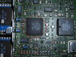
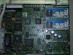
Looking at the main board, could be the cap I point with red arrow the culprit (seems to link the input hybrid for CH2 to the Tek IC) or am I far from the problem source ?

Thank you Brad.
 

Good work. That's progress.

Nothing looks wrong in your photograph.

1.

It's still a question what made the capacitor leak fluid. Typical causes:
(1) It was exposed to voltage greater than its rating (and may still be exposed).
(2) It may have carried overmuch current, even though at low voltage.

Either of the above faults could have occurred one time, or repeatedly. The currents could be DC or AC.

2.

Can you measure with your meter, to find any overvoltage conditions?

Do you see volt readings printed on the circuit board? Do they match your readings at test points (posts typically marked 'TP1', 'TP2')?

Do you have a service manual? Do your readings match the ones in the manual?
Etc.

3.

Since replacing it doesn't solve the problem, then another component apparently is still faulty. Can you detect any that have changed color?

The vertical deflection circuitry is still a suspect. Can you locate components in that section?

4.

Can you aim a hot air blower (hair dryer) on components, to speed up the problem?

5.

Can you find a solder blob where it shouldn't be? A metal screw sitting against exposed wires? Etc.

A magnifying glass will help you spot the tiny things.

6.

The problem started when you had certain devices hooked up, with certain scope settings. Did that configuration do something that could have brought on the problem? This is an unlikely cause but still merits some thought.

7.

Does the trace continue to display your incoming signal as it travels off the screen? When the 'waveform-Off' button is up or down?

It would help if you could see how a normal scope acts. Youtube has many videos showing scopes in operation.
 
Brad,

CH1 and CH2 work well till the moment CH2 trace oscillate and goes up.

The scope CH1 works flawlessly, even when the CH2 trace goes way, CH1 work well, it looses sync when triggering is attached to CH2.
After CH2 goes up, I change triggering to CH1 and the scope exhibit the CH1 curve without problems, can do delayed sweep, change resolution, time base, etc.

From the outside, to me as a user, it seems the logic unit of the scope receives a signal indicating the voltage of CH2 is huge thus the moving up trace.
Also when in auto mode and without any signal input, the scope select 10V/div for CH2 and only 50mV/div for CH1, which seems to indicate that the logic unit is receiving a "huge" signal input from CH2 and "none" signal for CH1 which is correct for CH1 but not true for CH2.

I am confused.

Can you shed some light to my "ramblings", thanks.
 

Can you shed some light to my "ramblings", thanks.

All of your observations are useful. You never know what detail may allow some expert to zero in on the problem.

And perhaps even your own application of the Sherlock Holmes approach. It enhances your ability to troubleshoot a problem.

Also when in auto mode and without any signal input, the scope select 10V/div for CH2 and only 50mV/div for CH1, which seems to indicate that the logic unit is receiving a "huge" signal input from CH2 and "none" signal for CH1 which is correct for CH1 but not true for CH2.

Yes, the auto-ranging may be faulty. Something could be adding a DC component falsely. Could be positive DC. Guess that rules out the high voltage that shoots the electron beam, because it is negative polarity. I could be wrong.

What if you give CH2 a small AC signal? Does the beam show the same amplitude as it moves upward? Or does amplitude increase?

What if you add a negative DC component to the signal? Can you alter it quickly enough to hold the beam onscreen any longer than usual? This could tell you whether the signal is still getting through as the fault happens, or whether the input amplifier gets disconnected entirely.

It will be helpful to give details as to what you mean, that the CH2 trace oscillates as it goes upward.

Does it rise gradually? Or in jumps?

You might want to shoot a video and put it on Youtube. This is what one poster did to clarify the problem in his oscilloscope. He put the video on Youtube and posted a link here so we could observe. It conveyed much more informative than words, or a photograph.
 

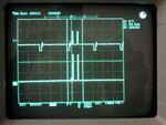
Here it is a video of the running CH2 trace: https://youtu.be/Lsc5KPiC5Z0

I hope it shed more light about the problem.

For now will read your post again and report back. Thanks.
 

As the CH1 is working and it is identical to CH2. Try to identify the signal path and compare the signals point by point. Look for a different DC offset and you will identify the stage that is malfuncioning. If the problem changes when you switch the vertical range switch try to identify the "DC balance" circuit. This is easy if you have a schematic (please post it if you have one) if not, chances are that the layout for the two channels is the same.
Freezing spray (as said before) should restore the working condition, may be that you are not appliying it at the right place. Start tracking the signal path right at the input BNC and work untill you reach the ADC.
Good luck
 

Here it is a video of the running CH2 trace:

1.

The self-diagnostic is performed early in the video. It says 'passed'. Can you make it perform a diagnostic after the CH2 trace rises off the screen? Does it report an error?

2.

The video shows the trace unchanged in amplitude as it rises upward. This implies that the input stage is stable.

The video shows the trace rises upward smoothly, not in increments. This implies that the auto-range stays on the same range.

3.

It would appear that the vertical deflection goes crazy as it heats up, pulling the beam offscreen.
It might be caused by a transistor going into thermal runaway.
I don't know if this is connected to the other issue you state, that the auto-range sets itself to a reduced sensitivity even with no signal.

It's a question how the auto-range decides to step down its sensitivity.
Does it detect that the vertical deflection voltages are getting too strong?
Or does it detect that the signal itself is too strong before it reaches the vertical deflection stage?

4.

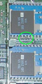
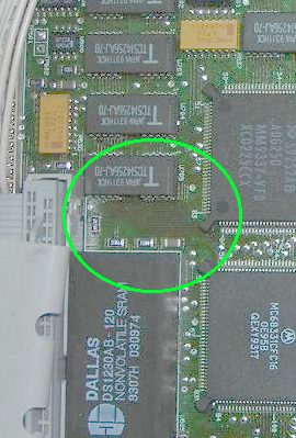
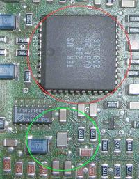
Looking closer at your photograph. There is what looks like silvery wires at the edge of a circuit board (inside the green circle).

2410665700_1352829627.jpg


The other twin board does not have it.
I suppose those boards operate the high-voltage beams, because they are identical, and they have what look like heavy duty components.

Can you verify whether the silvery object(s) are supposed to be there?

5.

You might want to post a photograph of the other side of the scope innards.
 

Thank you Albert for your reply.

No, I don't have a schematics of the scope, I do have the service manual. The manual has some flowcharts and describe how the things work, but has no TP voltages, nothing that can help me solve this puzzle.

I own the scope since last wednsday ( bought it for my RC hobby) and it arrive without any errors in the log.
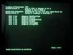
Now, if I do a diagnostic test the errors are shown in the error log. Check the pic attached

**broken link removed**Erros_TDS320_Nov9.JPG

The scope does the Power ON check without any error (as you can see in the video uploaded) and CH1 and CH2 both working good.

Yesterday, when I strip down the scope and change the electrolytic smd caps from the frontal board and since the scope enclosure was "open", I did try to follow the signal with my pc-sound-oscope (useless exercise).
Then when I re-assembled the scope and turn it on the CH2 trace withstand about 5 minutes (It let me think that was cured...) then sadly it went away...

Today the various tests I did, CH2 trace sweep for seconds, most of the times didn't reach the minute time, so why the 5 minutes??

I don't have freezing spray, but when manipulating the scope pcb's I didn't feel excessive temperature raising but didn't want to deliberately touch the ic's, so not a definitive answer.

- - - Updated - - -

Brad,

1. In the post before, I upload the result of the diagnostic test.

2. Ok!

3. As you said, could the vertical deflection goes crazy as it heats up, pulling the beam offscreen but leaving CH1 trace working without a itch? :confused:
Can the auto-range work independently for each channel? :confused:
Is this auto-range feature internal to the scope or is the "autoset" button you are refering?

4. that stage of teh scope is "closed" open box, I remove the lid to take the picture, what you select in the pic is a piece of the lower box that we twist to fix the upper lid.
As far as I understand, those boards are what TEk call input hybrid amplifiers and attenuators, one for each channel.

5. the rest of the scope boards are the PS, the video display board , the IO board (GPIB, rs232 and centronics) and the front board.
some pics:
Frontal pcb board (check the replaced caps)
DSCN2792_2.JPG
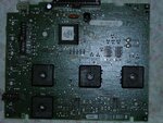
The main board with the lid on
DSCN2771_2.JPG
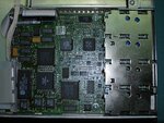
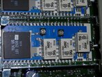
The hybrid board for CH2
DSCN2777_2.JPG
 

The recent photos seem okay. Your first photo shows what looks like a burned area. (Circled in green.) Do you spot any trouble there?

7326886900_1352883527.jpg


Yesterday, when I strip down the scope and change the electrolytic smd caps from the frontal board and since the scope enclosure was "open", I did try to follow the signal with my pc-sound-oscope (useless exercise).
Then when I re-assembled the scope and turn it on the CH2 trace withstand about 5 minutes (It let me think that was cured...) then sadly it went away...

Today the various tests I did, CH2 trace sweep for seconds, most of the times didn't reach the minute time, so why the 5 minutes??

It may have to do with the new caps being at zero the first time you powered up.

Which leads to another possibility: Suppose the auto-range (by auto-range I mean the circuit that decides how many volts per grid division)...
contains a sample-and-hold peak-detector circuit? This is typically based on a capacitor. (I don't know, for all I know it is a digital sample and hold.)

Suppose the capacitor charges immediately to a high level on power-up, due to... overly high voltage?... inside the IC. Then it stays high. It fools the auto-range into thinking you are applying a huge signal (as you already thought is happening).

After a minute the high voltage heats up other components (either in electrical contact, or in physical contact in the same IC). This sends the CH2 trace off the screen.

Remember that the old capacitors burst. This is often caused by overly high voltage. You have to track down this problem, in order to fix the scope.

This is only an effort at brainstorming on my part.

I don't have freezing spray, but when manipulating the scope pcb's I didn't feel excessive temperature raising but didn't want to deliberately touch the ic's, so not a definitive answer.

Try a bit of ice on them. You may even get lucky enough to cool the right component, which could bring the CH2 trace back down the screen.

Or apply ice as you power-up. You'll try to notice if there is a longer delay before the problem occurs.

Whatever the hot component turns out to be, your original problem might be elsewhere. Example, a fused voltage regulator.

You have a chance to catch the problem, since the unit operates normally while it is cool.

A bit of clean water shouldn't harm the low voltage circuitry, but it is vital that you keep water away from the high voltage wiring, lest it travel to other components and ruin them.

Have you located the high voltage generator circuits?
 
Following your ideas, I remove the main board from the scope and gave it a good cleaning with ethanol, followed by deionized water and some time under the sun to dry it out.

Reassembled the scope and, sadness, the CH2 trace goes up in a question of seconds.

A couple of hours later, power on the scope again and the CH2 trace didn't go away.

Nice!

Work with the scope for five straight hours without any problem, AUTOSET button worked, all the commands work well.

see for your self: IMG557.jpg


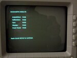
Decide to run the diagnostic tool and: IMG556.jpg


Then, in the end of the night, I turn the unit off.

Wait some moments and turn the scope again ON.

WTF!

The CH2 trace was again out in the limbo, my scope loose again CH2 trace.

I am leaning now for a software problem, what do you think about this crazy idea??

If it were a thermal problem, the scope couldn't work for more than 5 hours straight without loosing CH2 trace.

From the above, what you folks thing about this events?
 

Following your ideas, I remove the main board from the scope and gave it a good cleaning with ethanol, followed by deionized water and some time under the sun to dry it out.

Reassembled the scope and, sadness, the CH2 trace goes up in a question of seconds.

A couple of hours later, power on the scope again and the CH2 trace didn't go away.

Nice!

Work with the scope for five straight hours without any problem, AUTOSET button worked, all the commands work well.

This is a lucky break. By removing/cleaning the board, you restored normal operation. I assume it was the same board that had the burst capacitors?

The problem was gone all the while you kept the scope on. After you shut it off and switched it back on, the problem came back.

I think the problem has to do with the same overvoltage condition that caused the capacitors to burst (assuming they burst from being exposed to overvoltage). The condition remains after the scope is shut off.

Then on startup it causes the logic unit to make a faulty decision because it believes a huge signal is present.

The CH2 flies off the screen, either due to the same overvoltage heating up a component, or because the logic unit eventually goes into runaway in amplifying the signal.

When you removed and cleaned the board, it probably discharged all capacitors. Next time you turned on the scope, everything was at zero.

Go back to where the capacitors went bad. There may be a bad component which puts a charge on them. The voltage may be too high during operation, or, maybe it is supposed to be discharged when you shut off the scope.

Measure voltage on each capacitor at all stages of operation: When the scope is off, at power-up, after two minutes, etc.

You want to make sure the caps are not exposed to the same overvoltage that must have ruined the old capacitors. (If the new ones have not already been affected for the worse.)

Also try discharging the capacitors, to see if it cures the problem. Discharge them while the scope is off, and while it's running. Use a low ohm resistor. Don't short the terminals lest you draw overmuch current through a nearby component and ruin operation for good.

At all times watch to see what happens.

Anything you observe could lead to diagnosing the problem.
 
Brad, You're the man!

Thank you for your time.

Using an ice cub inserted in two plastic bags, I found the apparent culprit.

Here it is, surrounded by a red circle:

DSCN2806_2.JPG

Now, If the chip is performing its tasks but is becoming hot, this could indicate an increased voltage as power supply or other unknown problem.

How can I debug the surroundings of the chip?

And if the chip is heating till it lead to CH2 trace suspension by the following systems, why CH1 isn't also affected?

EDIT:
Without the pin out of the Tek ic, I measured the voltage between each leg of the chip and GND (with the scope working and no CH2 trace), two or three pins with +4.94V, three or four pins with -5.02V, some with +2.xV, very few with +/-0.2V and several with 0V

If the chip nominal voltage is 5V (unknown so far), I can't see any problem here, what do you think?

EDIT#2
The caps I replaced were in the frontal pcb (the one with the control buttons, pots and switches) the worst cap was doing the "waveform OUT" button and the other cap the "Trigger 50%" button.
Both buttons work now flawlessly.
 
Last edited:

Great news. Finding the problem is half the battle. At least you found one problem anyway.

The volt readings do not sound as though the chip has fused innards.

I was going to recommend that you check all around the IC circled in red. Look for broken traces, hairline cracks in solder joints, etc. Especially any component connected to it.

Looking at your higher resolution photo. There appears to be a missing or broken component close to that IC. (Indicated by green circle.)


It doesn't have the same broad silvery ends as other components. See if it is all right.

If it broke away, look for its remains all around inside the enclosure. Look closely to see if you can find it wedged anywhere.

Also look at nearby components for signs that they were knocked on with tools, etc.

Picture what the previous owner might have done. Often someone will unload a piece of equipment if it starts to go bad. He might have opened it, tried to fix it, and realized he could not. Do you see any signs of previous tampering?
 
]As far as I understand it, the scope has arrived in a pristine status, very well packed, with no signs of internal tinkering.

The component you point is a strange one, it look like a fat capacitor but with its thin terminals and red sides its different from the other smd caps.

DSCN2808_2.JPG
 

Attachments

  • DSCN2808_2.JPG
    DSCN2808_2.JPG
    302.5 KB · Views: 171
Last edited:

Brad,

New info!

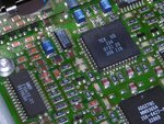
I measured the voltages of each pin of the chip and working with a cube of ice I found that the problem is associated with the voltage of pins 30 and 31 (check the pic attached)

The voltage of the pins change from -0.04V to +0.37V(pin 30) and simultaneously from -0.43V to -0.95V (pin 31).

This change remove CH2 trace from the display because the chip "unconnect" CH2 input.

Now, looking carefully to the pcb board I couldn't find any traces going to pins 30 and 31 (I have yet to look underneath the board)

Check the voltages of the remain pins when the change occur but was unable to see significant changes (less than 0,01V) so I really don't know what made pin 30 and pin 31 voltages change.


Any clue?

FSCN2810_2.JPG
 

Yes, sometimes that's the only way Kojak can find the bad guy... by checking down every street and avenue.

You're hoping the problem is not inside the IC. This could be the case where a gold wire inside breaks contact with the wafer as things heat up.

If the IC heats up abnormally then the problem might still be elsewhere. Guess it's hard to be sure what is the normal heat.

With luck it's outside the chip. A borderline solder connection under a pin. A hairline break in a trace. Try pressing down on each pin one at a time. See if you can make the problem come and go.

Can you press on the board anywhere to make the problem come and go? Flex the board? Tap the board?

Can you press on the chip to make the problem come and go?

It may come down to physically flexing the chip in hopes of maintaining electrical contact. Can you wedge a toothpick under the IC to make the problem come and go? (Guess you know you shouldn't use a steel needle.)

You'll need to get at the other side of the board to examine the traces. Sometimes there are traces going between layers inside of the board where you can't see them.
 
Status
Not open for further replies.

Part and Inventory Search

Welcome to EDABoard.com

Sponsor

Back
Top