boylesg
Advanced Member level 4
- Joined
- Jul 15, 2012
- Messages
- 1,023
- Helped
- 5
- Reputation
- 10
- Reaction score
- 6
- Trophy points
- 1,318
- Location
- Epping, Victoria, Australia
- Activity points
- 11,697
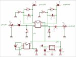
Could anyone point me in the direction of a suitable discrete transistor amplifier schematic that would be suitable for amplifying the audio signal from an ipod before it goes into the control pin of a 555. Preferably using BC547, BBC548, BC549, BC557, BC558, BC559, C1815, A1015, BC327 or BC337.....all of which I have plenty of.
Judging by the datasheet for NE555, I ideally need the audio signal to vary around 5V up to my 12V rail. But I am doubting that you would get that sort of voltage level from the average set of ear pohone speakers.
There are so many different types and classes of amplifier, I have no idea where to begin.