Continue to Site

Welcome to EDAboard.com

Welcome to our site! EDAboard.com is an international Electronics Discussion Forum focused on EDA software, circuits, schematics, books, theory, papers, asic, pld, 8051, DSP, Network, RF, Analog Design, PCB, Service Manuals... and a whole lot more! To participate you need to register. Registration is free. Click here to register now.

[SOLVED] I get Mikrobasic error 'there is not enough ROM space' during compiling

Status
Not open for further replies.

SparkyChem

Member level 3
Joined
Apr 22, 2010
Messages
57
Helped
0
Reputation
0
Reaction score
0
Trophy points
1,286
Location
Lima, Peru
Activity points
2,084
Hello there, the following it is the code i am using from Mikrobasic tutorials and i have adapted it to work on PIC16F676 but it cannot work. Each time keeps telling me there is not enough ROM space. What am i doing wrong?. It seems Mikrobasic consumes a lot from microcontroller memory. Is there anyway to bypass this?. Thanks.

Code:
program F676_exp
' Declarations section
'******************************************************
dim LCD_RS as sbit at RC4_bit ' Lcd
LCD_EN as sbit at RC5_bit
LCD_D4 as sbit at RC3_bit
LCD_D5 as sbit at RC2_bit
LCD_D6 as sbit at RC1_bit
LCD_D7 as sbit at RC0_bit
LCD_RS_Direction as sbit at TRISC4_bit
LCD_EN_Direction as sbit at TRISC5_bit
LCD_D4_Direction as sbit at TRISC3_bit
LCD_D5_Direction as sbit at TRISC2_bit
LCD_D6_Direction as sbit at TRISC1_bit
LCD_D7_Direction as sbit at TRISC0_bit ' LCD
dim text as string [16]   ' text string
dim ch, adc_rd as word    ' ch, adc_rd word
dim tlong as longword     ' tlong, longword
sub procedure settings
CMCON=7
ANSEL=%00000001
ADCON1=%00110000
ADCON0=%10000001
TRISA=%000001
INTCON = 0                ' all interrupts disabled
TRISC = 0   ' PORTC is output
end sub
main:
'   Main program
settings
Lcd_Init()                ' LCD
Lcd_Cmd(_LCD_CURSOR_OFF)  ' LCD (off)
Lcd_Cmd(_LCD_CLEAR)       ' LCD command (clear LCD)
text = "mikroElektronika" ' First message
Lcd_Out(1,1,text)         ' First message, first line
text = "LCD example"      ' Second message
Lcd_Out(2,1,text)         ' Second message, second line
Delay_ms(500)
text = "Voltage="         ' Third message
while 1                   ' Loop
  adc_rd = ADC_Read(0)    ' A/D conversion. RA0 input.
  Lcd_Out(2,1,text)       ' Result second line
  tlong = adc_rd * 5000   ' Milivolt
  tlong = tlong / 1023    ' 0..1023 -> 0-5000mV
  ch = (tlong / 1000) mod 10 '
                             '
  Lcd_Chr(2,9,48+ch)      '
  Lcd_Chr_CP(".")         '
  ch = (tlong / 100) mod 10 '
  Lcd_Chr_CP(48+ch)         '
  ch = (tlong / 10) mod 10  '
  Lcd_Chr_CP(48+ch)         '
  ch = tlong mod 10         '
  Lcd_Chr_CP(48+ch)         '
  Lcd_Chr_CP("V")           ' Show "V"
  Delay_ms(1)               ' 1mS delay
wend
end.
 

its very simple....u have selected the wrong chip for ur program. all u need to do is to change the microcontroller that u hav their in ur design to a controller with enough flash memory for the program that u are developing. say for example 16F877A,873A etc they hav 8KB and 4KB of memory respectively. and they also hav an embedded adc unlike the 16F676 that u hav opt for.....hope this helps

Sequel
 

Change the code a little.

Change these 2 lines:
Code:
  tlong = adc_rd * 5000   ' Milivolt
  tlong = tlong / 1023    ' 0..1023 -> 0-5000mV

to

Code:
 tlong = (adc_rd * 5000) >> 10

Also, declare a 16-bit variable at the beginning of the code:

Code:
dim tempt as word

After the line:
Code:
 tlong = (adc_rd * 5000) >> 10

add:
Code:
tempt = tlong

Then replace this:
Code:
ch = (tlong / 1000) mod 10 '
                             '
  Lcd_Chr(2,9,48+ch)      '
  Lcd_Chr_CP(".")         '
  ch = (tlong / 100) mod 10 '
  Lcd_Chr_CP(48+ch)         '
  ch = (tlong / 10) mod 10  '
  Lcd_Chr_CP(48+ch)         '
  ch = tlong mod 10         '
  Lcd_Chr_CP(48+ch)

with this:

Code:
ch = (tempt / 1000) mod 10 '
                             '
  Lcd_Chr(2,9,48+ch)      '
  Lcd_Chr_CP(".")         '
  ch = (tempt / 100) mod 10 '
  Lcd_Chr_CP(48+ch)         '
  ch = (tempt / 10) mod 10  '
  Lcd_Chr_CP(48+ch)         '
  ch = tempt mod 10         '
  Lcd_Chr_CP(48+ch)

Make the modifications I showed above and try again.

Hope this helps.
Tahmid.
 

Hello tpetar, i am using the 3.2 version of the software.

its very simple....u have selected the wrong chip for ur program. all u need to do is to change the microcontroller that u hav their in ur design to a controller with enough flash memory for the program that u are developing. say for example 16F877A,873A etc they hav 8KB and 4KB of memory respectively. and they also hav an embedded adc unlike the 16F676 that u hav opt for.....hope this helps

Sequel

To sequel. This application as said by tpetar is less than 2kb and it should run without any problems in that microcontroller.

This program is under 2KB and he select right uC 16F676.

Ditto.

Change the code a little.

Change these 2 lines:
Code:
  tlong = adc_rd * 5000   ' Milivolt
  tlong = tlong / 1023    ' 0..1023 -> 0-5000mV

to

Code:
 tlong = (adc_rd * 5000) >> 10

Also, declare a 16-bit variable at the beginning of the code:

Code:
dim tempt as word

After the line:
Code:
 tlong = (adc_rd * 5000) >> 10

add:
Code:
tempt = tlong

Then replace this:
Code:
ch = (tlong / 1000) mod 10 '
                             '
  Lcd_Chr(2,9,48+ch)      '
  Lcd_Chr_CP(".")         '
  ch = (tlong / 100) mod 10 '
  Lcd_Chr_CP(48+ch)         '
  ch = (tlong / 10) mod 10  '
  Lcd_Chr_CP(48+ch)         '
  ch = tlong mod 10         '
  Lcd_Chr_CP(48+ch)

with this:

Code:
ch = (tempt / 1000) mod 10 '
                             '
  Lcd_Chr(2,9,48+ch)      '
  Lcd_Chr_CP(".")         '
  ch = (tempt / 100) mod 10 '
  Lcd_Chr_CP(48+ch)         '
  ch = (tempt / 10) mod 10  '
  Lcd_Chr_CP(48+ch)         '
  ch = tempt mod 10         '
  Lcd_Chr_CP(48+ch)

Make the modifications I showed above and try again.

Hope this helps.
Tahmid.

I changed the code, and it does work. I think the trick was introducing the 16-bit variable.
 

Yes, it was. Avoid using large variables unless absolutely necessary. Here, your result would be less than 5000. So, instead of carrying out calculations on a 32-bit variable, calculations were done on a 16-bit variable, which was enough.

Just a tip: Also avoid using floating point calculations and divisions (and multiplication), especially by large numbers, unless absolutely necessary.

Although it works the simulation on Proteus it is some strange in terms of accuracy. When the pot is turned all way down the ADC conversion on LCD shows 0.000 Volts which is correct but, when it goes full high it does tell 4.995 and not 5.000. Why is that? Is it because of the limitations of the 10-bit conversion or is it because the code doesn't allow that to happen?. Is this related to the less 5000 you mentioned?
 

It's fine. It's supposed to be like that. It's a 10-bit ADC. So, it can have 1024 values (0 to 1023). So, with 5V reference, an ADC reading of 1 corresponds to (5/1024)*1000mV = 4.8828125mV. So, the maximum voltage that can be measured is [(1023 * 4.8828125)/1000]V = 4.995V. And that's what you get. You can't measure a voltage any higher than 4.995V (which we tend to round off to 5.00V).

Hope this helps.
Tahmid.
 
On 7 segs Re: I get Mikrobasic error 'there is not enough ROM space' during compiling

I've been trying to implement your previous P16F88 code on this project but i came across a bogus conversion.

While the digits do come out in the 7-segments as described before, it doesn't escalate up to 4.995 as on the LCD why would that be?. Can you take a look at the code.? Maybe i missed up something.

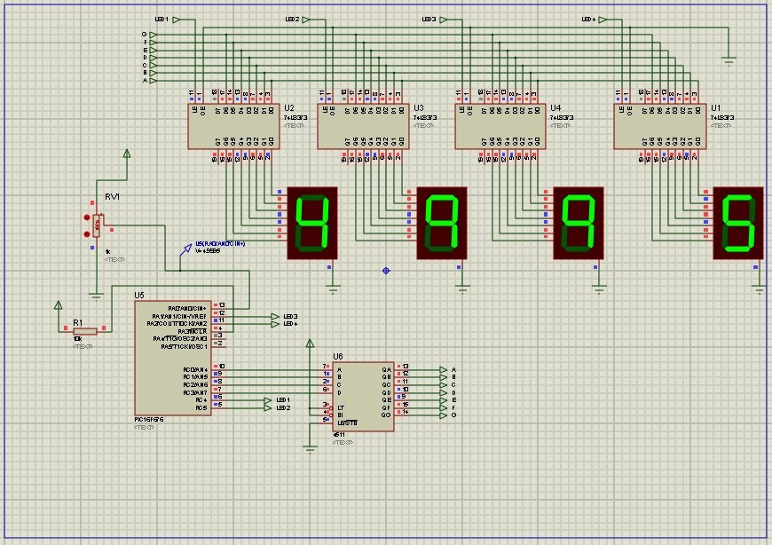
There is the animation at the bottom of what i got after doing the simulation on ISIS.

Thanks.:)
PD. I added a 4511 CMOS from RC0 to RC3 ports due to pinout limitations of the P16F676, so i changed the mask a little bit, i think that shouldn't be a problem.

Code:
program F676_expADC
' Declarations section
dim data7, num7 as byte
dim adc_rd, tempt as word
dim tlong as longword
dim digit as byte[4]
sub procedure send7 (dim value, seven as byte)
'Changed to Common Cathode Display
    PORTA = 0
    select case value
           case 0 data7 = 0
           case 1 data7 = 1
           case 2 data7 = 2
           case 3 data7 = 3
           case 4 data7 = 4
           case 5 data7 = 5
           case 6 data7 = 6
           case 7 data7 = 7
           case 8 data7 = 8
           case 9 data7 = 9
    end select
    PORTC = data7
    TRISA=1
    select case seven
           case 1
           RC4_bit = 1
           case 2
           RC5_bit = 1
           case 3
           RA1_bit = 1
           case 4
           RA2_bit = 1
           end select
end sub
sub procedure Settings
    CMCON=7
    ANSEL=%00000001
    ADCON1=%00000000
    ADCON0=%10000001
    TRISC=0
end sub
sub procedure delay2ms
    delay_ms(2)
end sub
main:
'   Main program
    Settings()
    while true
           adc_rd = ADC_Read(0)    ' A/D conversion. RA0 input.
           tlong = (adc_rd * 5000) >> 10
           tempt = tlong
           digit[0] = (tempt / 1000) mod 10 '
           digit[1] = (tempt / 100) mod 10
           digit[2] = (tempt / 10) mod 10
           digit[3] = tempt mod 10
           send7(digit[0],1)
           delay2ms()
           send7(digit[1],2)
           delay2ms()
           send7(digit[2],3)
           delay2ms()
           send7(digit[3],4)
           delay2ms()
     wend
end.
 

Attachments

  • P16F676_ADC.PNG
    P16F676_ADC.PNG
    72.3 KB · Views: 77

Please upload the Proteus DSN file.

Oh hello there. I the system doesn't allow me to upload *.DSN files so i uploaded to my putlocker account. (**broken link removed**) You can download it from there. I hope you can spot what is it wrong?. :)

Cheers
 

RAR file same as above.
 

Attachments

  • ADC_P16F676.rar
    17.9 KB · Views: 50

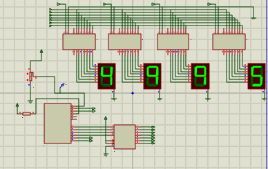
It works fine for me:

1688607700_1353150378.png


2620454000_1353150379.png

Hey man, can you upload the .mbas file and the .hex file you're using from mikroBasic?. I suspect maybe my version of mikrobasic or Proteus is not working it right. I checked the code twice and i still get the same error.

By the way during the simulation i got the following warning message from the log section (left bottom corner in ISIS), telling me "PIC12ADC PC=0x0013 ADC conversion clock period (5e-07) is possibly invalid for device clock frequency.", do you get the same too?.

Thanks in advance.:)
 

Here I've attached the project files, the hex file and the DSN file.

Yes, I do get that message. I'll look into it to find the reason.The odd part is that the message shows PIC12ADC, whereas it should show PIC16ADC. Anyways, I'll look into it.
 

Attachments

  • SparkyChem mikroBASIC ADC.zip
    115.7 KB · Views: 98

You should call ADC_Init() function in the initialization routine after ADCON settings. You have to set ADCON1 register.
 

You should call ADC_Init() function in the initialization routine after ADCON settings. You have to set ADCON1 register.

In his code, he uses the ADC_Read(0) function. For ADC_Read() function, ADC_Init() does not need to be called. ADC_Init() only needs to be called for ADC_Get_Sample().

The ADCON1 settings are not required as well, as mikroBASIC should do that as well. All he needs to do is, set the required values in ANSEL register (which he has done).
 

Status
Not open for further replies.

Part and Inventory Search

Welcome to EDABoard.com

Sponsor

Back
Top