Continue to Site

Welcome to EDAboard.com

Welcome to our site! EDAboard.com is an international Electronics Discussion Forum focused on EDA software, circuits, schematics, books, theory, papers, asic, pld, 8051, DSP, Network, RF, Analog Design, PCB, Service Manuals... and a whole lot more! To participate you need to register. Registration is free. Click here to register now.

[SOLVED] design tips for LED driver using power LEDS

Status
Not open for further replies.

sivaprasadgnair

Newbie level 5
Joined
Nov 9, 2012
Messages
8
Helped
0
Reputation
0
Reaction score
0
Trophy points
1,281
Location
mumba
Activity points
1,330
Hi guys,
I do have a query on design of LED driver For power LEDs.

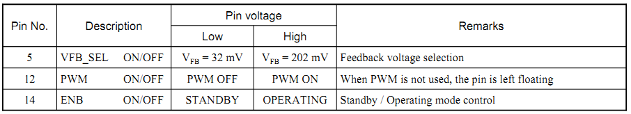
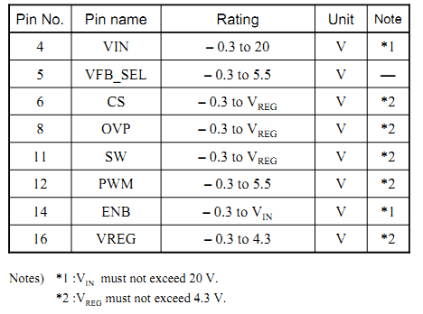
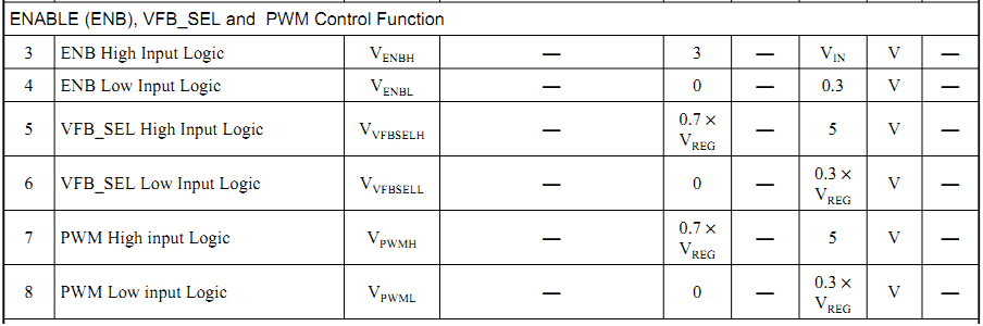
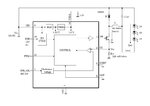
I am using a an30888a of panasonic as my LED driver for 3 LEDs of 3.25w each in series and power consumption of around 800mA.I am using it in Buck mode. But in data sheet of an30888a i am alittle bit confused with pins ENB,PWM and VFB/SEL. so please help me what to do with that pins.
 

But in data sheet of an30888a i am alittle bit confused with pins ENB,PWM and VFB/SEL. so please help me what to do with that pins.

These are all logic inputs. They get either a high or low signal.

1.

ENB is short for Enable. The datasheet says 'Standby On/Off control' or 'Standby operating mode control'.

2.

PWM means Pulse width modulation.
The datasheet calls it 'PWM dimming control'.
It says 'When PWM is not used, the pin is left floating.'

3.

VFB/SEL is 'Feedback voltage select.'

-----------------------------

The datasheet states a range of volt levels you can apply to these pins, which will be interpreted as a low, or as a high.

Keep in mind the safety guidelines which state the minimum and maximum volt level that you may apply at any pin.
 

Go to page 12 of the datasheet (www.semicon.panasonic.co.jp/ds4/AN30888A_AEB.pdf).

Low to VFB_SEL will set a feedback voltage of 32mV. High to VFB_SEL will set a feedback voltage of 202mV.
Low to PWM will disable Pulse Width Modulation. High to PWM will enable Pulse Width Modulation.
Low to ENB will set the device in standby mode. High to ENB will set the device in operating mode.

5008836300_1352528032.png


Go to pages 9 and 10 of the datasheet. You can see the allowable voltage ranges.

2311923200_1352527949.png


6226354500_1352527999.png


Hope this helps.
Tahmid.
 

hai Tahmid thanks for your replay. I will get back to you after my developments.
 

Status
Not open for further replies.

Similar threads

Part and Inventory Search

Welcome to EDABoard.com

Sponsor

Back
Top