Continue to Site

Welcome to EDAboard.com

Welcome to our site! EDAboard.com is an international Electronics Discussion Forum focused on EDA software, circuits, schematics, books, theory, papers, asic, pld, 8051, DSP, Network, RF, Analog Design, PCB, Service Manuals... and a whole lot more! To participate you need to register. Registration is free. Click here to register now.

PWM with PIC16f877A sample code in MikroC v5.0 and Proteus 7.5 SP3

Status
Not open for further replies.

marven2320

Junior Member level 1
Joined
Jan 28, 2012
Messages
15
Helped
0
Reputation
0
Reaction score
0
Trophy points
1,281
Activity points
1,394
Hi All!

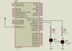
I am trying to work with PWM. I understand the concept of PWM but when I tried the mikroC sample for PWM at PIC16f877A it doesn't show any significant result. I configured the PIC16f877A project at 8MHz crystal so as the proteus project.

Code:
unsigned short current_duty, old_duty, current_duty1, old_duty1;

void InitMain() {
  //ANSEL  = 0;                         // Configure AN pins as digital
  //ANSELH = 0;
  //C1ON_bit = 0;                       // Disable comparators
  //C2ON_bit = 0;
  
  PORTA = 255;
  TRISA = 255;                        // configure PORTA pins as input
  PORTB = 0;                          // set PORTB to 0
  TRISB = 0;                          // designate PORTB pins as output
  PORTC = 0;                          // set PORTC to 0
  TRISC = 0;                          // designate PORTC pins as output
  PWM1_Init(5000);                    // Initialize PWM1 module at 5KHz
  PWM2_Init(5000);                    // Initialize PWM2 module at 5KHz
}

void main() {
  InitMain();
  current_duty  = 16;                 // initial value for current_duty
  current_duty1 = 16;                 // initial value for current_duty1

  PWM1_Start();                       // start PWM1
  PWM2_Start();                       // start PWM2
  PWM1_Set_Duty(current_duty);        // Set current duty for PWM1
  PWM2_Set_Duty(current_duty1);       // Set current duty for PWM2

  while (1) {                         // endless loop
    if (RA0_bit) {                    // button on RA0 pressed
      Delay_ms(40);
      current_duty++;                 // increment current_duty
      PWM1_Set_Duty(current_duty);
     }

    if (RA1_bit) {                    // button on RA1 pressed
      Delay_ms(40);
      current_duty--;                 // decrement current_duty
      PWM1_Set_Duty(current_duty);
     }

    if (RA2_bit) {                    // button on RA2 pressed
      Delay_ms(40);
      current_duty1++;                // increment current_duty1
      PWM2_Set_Duty(current_duty1);
     }

    if (RA3_bit) {                    // button on RA3 pressed
      Delay_ms(40);
      current_duty1--;                // decrement current_duty1
      PWM2_Set_Duty(current_duty1);
     }

    Delay_ms(5);                      // slow down change pace a little
  }
}

sample.png

Is there any configuration I missed for this sample to work?
Thanks!
 

You are not using any buttons at RA0, RA1, RA2, RA3. How can you increment/decrement the current_duty/current_duty1?

Hence the PWM is not varying.
 

You are not using any buttons at RA0, RA1, RA2, RA3. How can you increment/decrement the current_duty/current_duty1?

Hence the PWM is not varying.


I am not trying to vary the PWM.
I just want to see that the PWM is really working at a certain duty cycle specified in the code.
There must be a blinking of LEDs even without varying the PWM, right?
I cant see it blinking in my simulation.
 

post your proteus .dsn file and .hex file. zip and post.

Have you set the clock in proteus with the clock frequency you compiled the code for.

It is working. You are not able to see it properly, because you are using Red LED. Use Yellow LED. RED and Yellow leds, both blink.

Here is the simulation video.
 

Attachments

  • pwmsim.rar
    97.1 KB · Views: 89
Last edited:

Attached is the pwm.dsn and the pwmsample.mcppi along with the hex file generated in mikroC project.

Thanks!
 

Attachments

  • PWM.rar
    47.1 KB · Views: 98

I checked your files. It is working. See the simulation video of your files.
 

Attachments

  • pwmsim2.rar
    158.9 KB · Views: 90
I checked your files. It is working. See the simulation video of your files.

I didn't see it. Can you show me where should I view the simulation video you mentioned?
Thanks!

- - - Updated - - -

As you can see in the attached picture.
The PORTC and PORTB are all colored blue which signifies that its voltage output is zero.
It is always like that in my screen that's I cant see it working with the PWM code.
Can you show me where can I see those simulation video you mentioned?

Thanks!

- - - Updated - - -

I checked your files. It is working. See the simulation video of your files.

I saw your video attached. How come I can't see in my simulation?
Is there any settings in my computer to enable this?

Thanks!
 

Attachments

  • sample.png
    sample.png
    24.8 KB · Views: 83

May be you compiled the code for different clock frequency and you have set some other clock frequency in proteus.
 

May be you compiled the code for different clock frequency and you have set some other clock frequency in proteus.

Probably not. His simulation file with his generated hex file and his set clock frequency does generate the PWM signals. And, if with wrong clock frequency, some output should be observed - just won't have the correct frequency.
 

Thanks for the help everyone!
I just updated my proteus version and its now working fine.
 

Status
Not open for further replies.

Similar threads

Part and Inventory Search

Welcome to EDABoard.com

Sponsor

Back
Top