lhlbluesky
Banned
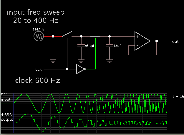
in S/C bandpass filters, the center frequency f0 can be tuned by clock frequency fclk, and normally, fclk is much larger than f0, 50 times or bigger. however, in some cases, f0 is just the input signal frequency (ex:in ir receiver, f0 is the carrier frequency), f0=fsignal, then, in half period of input signal, fclk works 25 cycles, so, how to decide the transient output for S/C filter? if tuning the frequency of fclk to obtain desired f0, then in half period of input signal, fclk may be not integral cycles, can this cause a wrong transient result?
besides, in S/C bandpass filters, how to simulate the AC response (center frequency f0, Q, etc), just as the continuous filter (in hspice)?
thanks.
besides, in S/C bandpass filters, how to simulate the AC response (center frequency f0, Q, etc), just as the continuous filter (in hspice)?
thanks.