Continue to Site

Welcome to EDAboard.com

Welcome to our site! EDAboard.com is an international Electronics Discussion Forum focused on EDA software, circuits, schematics, books, theory, papers, asic, pld, 8051, DSP, Network, RF, Analog Design, PCB, Service Manuals... and a whole lot more! To participate you need to register. Registration is free. Click here to register now.

schottky diode simulation for rectification using ADS

Status
Not open for further replies.

khaled1990

Newbie level 5
Joined
Dec 29, 2010
Messages
8
Helped
0
Reputation
0
Reaction score
0
Trophy points
1,281
Activity points
1,342
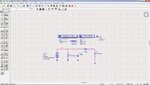
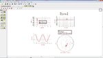
i am working on a rectifier circuit for a rectenna system , as a beginning i want to simulate the frequency response of schottky ( sms2820 ) diode using ADS , what is the suitible type of simulation and if any one could help me with a suitable circuit design i'll be greatfull .
 

Schottky diodes are forward biased components and bias conditions define high frequency behaviour of the diode.That's why you should use large signal models with proper bias and HB simulation will compute frequency response of your circuit.
Don't use AC or S-Parameters simulation,they will be erroneous.
 
Bigboss thank you for your concern , but i am new to ads , so if you could help me with further explanation , concerning the circuit diagram the type of source and if i need to do impedance matching,i didn't design the rectifier circuit yet, as part of my work i should compare between 3 different types of schottky diodes . but i dont know the suitable circuit diagram for computing the frequency response.
 

You can design to follow me and i think those the pictures. It can help you.


Good luck
 

Attachments

  • Schematic.jpg
    Schematic.jpg
    364 KB · Views: 462
  • i_o signal.jpg
    i_o signal.jpg
    217.1 KB · Views: 391
krisz , first of all thank you for your concern . i have a general question in the harmonic balance ,, when you plot the magnitude of the output voltage , it difers from the voltage obtained in the time domain signal , so do you know whats the differnece between them or which one is the desired voltage at the output ?
 

please send me the photos (ADS schematics) how to use schotky diode large signal simulation : Exp freq 7.5 GHz, Dc bias 0 to 2 V , LO power =10 dBm

- - - Updated - - -

My mail ID: dubelalbahadur@gmail.com, Please send the ADS schematics
 

Status
Not open for further replies.

Part and Inventory Search

Welcome to EDABoard.com

Sponsor

Back
Top