Continue to Site

Welcome to EDAboard.com

Welcome to our site! EDAboard.com is an international Electronics Discussion Forum focused on EDA software, circuits, schematics, books, theory, papers, asic, pld, 8051, DSP, Network, RF, Analog Design, PCB, Service Manuals... and a whole lot more! To participate you need to register. Registration is free. Click here to register now.

[Interview] Timing Boundary Constraints [please check]

Status
Not open for further replies.

ivlsi

Advanced Member level 3
Joined
Feb 17, 2012
Messages
883
Helped
17
Reputation
32
Reaction score
16
Trophy points
1,298
Activity points
6,868
Hi All,

Here is a question from my last interview:

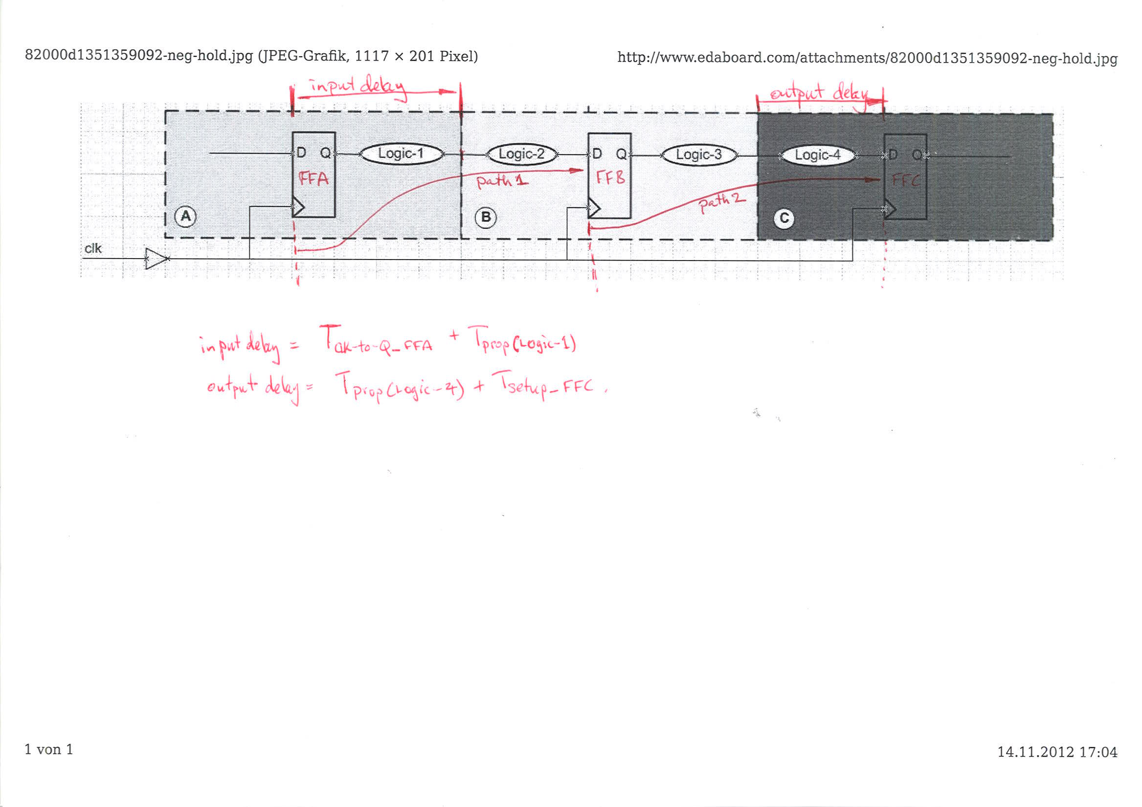
GIVEN: Blocks A, B, and C (see the picture below - click on it in order to zoom it in)
Block 'B' timing requirements:
Setup Time: 4nSec
Hold Time: 2nSec
Clock Period: 20nS
Block 'C' timing requirements:
Setup Time: 3nSec
Hold Time: 1nSec
Clock Period: 20nS

REQUIRED: Define the boundary constraints [input/output delays] for the Block 'B'.

neg-hold.jpg

Here is my solution:
create_clock -name CLK -period 20 -waveform {0 10} {get_port <port_name>}
set_input_delay -max (20-4=16) -clock {get_clock clk} -port {get_port <port_name>}
set_input_delay -min -2 -clock {get_clock clk} -port {get_port <port_name>}
set_output_delay -max 3 -clock {get_clock clk} -port {get_port <port_name>}
set_output_delay -min -1 -clock {get_clock clk} -port {get_port <port_name>}

Please pay your attention that I put HOLD constraints as negative for both INPUTS and OUTPUTS. Is that correct? Please give your comments.

Thank you!
 

Any response? Comments?
 

Are you sure this was the question you were asked? The set_input_delay and set_output_delay commands are needed to model the timing of your design in the context of the larger system. The specification of the clock is ok.

The input delay specification for block B should come from the clock to output time of the register in A plus the combinatorial delay of the Logic-1 block, so you need both of these numbers in order to write down the actual command. Having a minimum and maximum value (e.g. fast and slow process values) for each will enable ou to specify the -min and -max options for the hold and setup analyses respectively.

set_input_delay -max Slowest( Tclk-to-q + Tlogic-1 ) -clock {get_clock clk} -port {get_port <port_name>}
set_input_delay -min Fastest( Tclk-to-q + Tlogic-1 ) -clock {get_clock clk} -port {get_port <port_name>}

To specify the output delay, you need to know the combinatorial delay of Logic-4 and the setup time required for the register in block-C.this last one, you have, but it's only one number.

set_output_delay -max Slowest( Tlogic-4 + Tsetup-reg-c) -clock {get_clock clk} -port {get_port <port_name>}
set_output_delay -min Fastest(Tlogic-4 + Tsetup-reg-c) -clock {get_clock clk} -port {get_port <port_name>}

Note that when implementing your block (B) the tool will insert buffers to delay the signal or the clock in order to meet the constraints set with these commands, if it can.

I can see that this question is bothering you (multiple references in unrelated threads). Perhaps you can reply outlining in a bit more depth your thought processes in writing down the answers you gave.

Note also that a negative input delay is a valid constraint: it just means that the data become stable before the clock edge.


Best wishes,
sharted
 

Are you sure this was the question you were asked
Sure. This question is very practical and seems a famous one... Let's say you need to synthesize the Block-B, so that its timing would meet the connected blocks 'A' and 'C', which were already synthesized. Each of these blocks (A, B, and C) have got the timing budgets (see the timing requirements in the first post on this thread).

The set_input_delay and set_output_delay commands are needed to model the timing of your design in the context of the larger system
Sure, in respect to connected modules / signals. These commands actually define min/max delays on the timing paths of the considered design (design where the constraints are applied to).

I can see that this question is bothering you (multiple references in unrelated threads
Yes, it is. I hope that constraints, which I have put, they are correct. I would also like to receive some approvals from more experience engineers.

My concern on the input/output min delays (hold) definition. Are they correct?
By defining the input min delay for '-2', I want to force the tool to implement the min delay of 2ns on the Logic-2.
By defining the output min delay for '-1', I want to force the tool to implement the min delay of 1ns on the Logic-3.

Is that correct?

- - - Updated - - -

negative input delay is a valid constraint: it just means that the data become stable before the clock edge
I interpretative this in another way: The data might be changed before the active clock edge (this way the data should be delayed against the clock internally inside of the cell).
 

Sure, in respect to connected modules / signals. These commands actually define min/max delays on the timing paths of the considered design (design where the constraints are applied to).

No. The input and output delays refer to the delays external (i.e. in A and C) to the block that you're implementing (i.e. B in this example). I've drawn these on your circuit diagram:


I've clearly marked these as input delay and output delay.

In that respect, combined with the clock period and the setup & hold times of the flip flops from the technology, you indirectly constrain the combinatorial path delays of Logic-2 and Logic-3. I'd suggest you look this up in the Synopsis Timing Constraints and Optimization User Guide here.

I'm sure a more experienced engineer would be happy to tell you the same thing.

Are you sure this wasn't a trick question? Had I been presented with this I would have to answer that without the information detailed in my first response, I'm unable to write down numeric values for the input and output delays. Perhaps somebody can see something I'm missing.

sharted.
 

you indirectly constrain the combinatorial path delays of Logic-2 and Logic-3
That exactly what I wanted to do!

I'm sure a more experienced engineer would be happy to tell you the same thing.
I consider you as an experienced one :wink:

Are you sure this wasn't a trick question?
I think this question is a tricky one since it require to define internal timing of Block-B by external constraints (input/output delay).

Please go over my constraints (you would find them in the first post) and try to to see what delays will be implemented on the Logic-2 and Logic-3 paths.

I look forward to your response.
 

My concern on the input/output min delays (hold) definition. Are they correct?
By defining the input min delay for '-2', I want to force the tool to implement the min delay of 2ns on the Logic-2.
By defining the output min delay for '-1', I want to force the tool to implement the min delay of 1ns on the Logic-3.

Is that correct?

No and no.

Either:
1) you haven't read my responses;
2) you haven't understood them and aren't aware of it;
3) you're doing this on purpose.

Are you trolling me?
 

Status
Not open for further replies.

Part and Inventory Search

Welcome to EDABoard.com

Sponsor

Back
Top