Continue to Site

Welcome to EDAboard.com

Welcome to our site! EDAboard.com is an international Electronics Discussion Forum focused on EDA software, circuits, schematics, books, theory, papers, asic, pld, 8051, DSP, Network, RF, Analog Design, PCB, Service Manuals... and a whole lot more! To participate you need to register. Registration is free. Click here to register now.

My Atmega32 getting Confused when i switch on a 220 AC lamp

Status
Not open for further replies.

baby_1

Advanced Member level 1
Joined
Dec 3, 2010
Messages
415
Helped
1
Reputation
2
Reaction score
1
Trophy points
1,298
Activity points
4,277
Hello
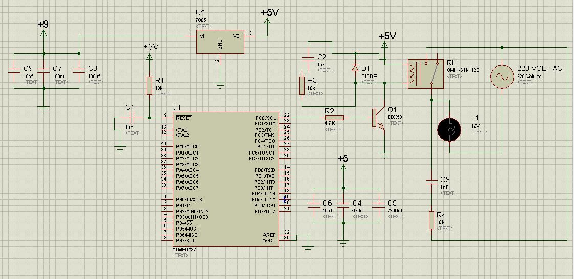
i create this below circuit but it has a big problem

My MCU works fine until after 2-3 seconds that i switched on an AC 220V 1A lamp.
as i tested before when i disconnect the AC voltage source from my circuit works fine (it switch on the relay and do the functions properly)

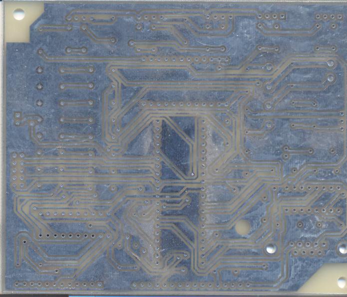
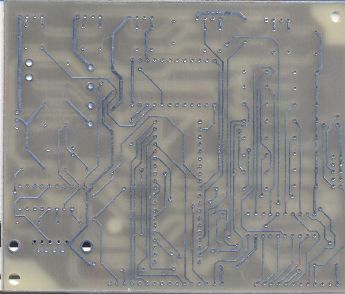
what is my wrong?(i forget to say i polygon my PCB)

2291263700_1351089297.jpg
 

May be you must use a different power supply for relay...
Or use the 9V power rail...
Why you use a 8A IC transistor in darlington for a >=150mA relay??? (This is not affect the circuit).
Show your pcb!!!
 
Last edited:

It is definitely bad to supply the relay from the regulated supply of the microcontroller, connect it to the unregulated 9v supply through a resistor or use a higher rating relay
 
Hello
Here is my pcb

I connected only the circuit components that i show above ( i check the voltage from each elements and pins and they were correct)


my relay connect to my pcb via wire and it is not in my board.
i checked and supplay relay with another power supplay ( i share the grounded ) but it still has problem.
 

I don't believe that any of the criticisms related to relay supply and similar hits the point. It's no problem to use an oversized switch transistor to drive a relay. Relay supply voltage can be selected according to the design prerequisites and requirements, as long as it doesn't overload the respective supply node. I guess that's not the case here, but we should know about the relay specification. Also primary relay flywheel cicruit is O.K. The additional primary RC snubber is effectively useless.

But. There's no meaningful 230V snubber, 10K/1nF is similar to no snubber. The basic problem of the board is however insufficient ground (and possibly Vcc) wiring and may be unsuitable bypassing. The said "polygons" or copper pours don't seem to support the ground net and are completely scattered. I would prefer to see a visualization of power and ground nets in a gerber viewer or the CAD tool to determine the actual supply wiring quality. Single chip processors are rather easy to please in this regard as far as regular operation is concerned, because they don't expose fast signals to the outer world. Even active EMC must not be a problem. But passive EMC, particularly ESD strength and suppressing of burst signals depends on layout quality and transient suppression in external interfaces and supply connections.
 
I don't mean to argue but I wouldn't expect supplying a relay from a regulator that also feeds a microcontroller to be a good practice.
So as long as the regulator can support both loads (mcu +relay )you say there is no problem at all and this scheme should be used without hesitation?

Alex
 

No problem to word your doubts. I don't claim to give final answers, just was telling how I handle these things, A relay coil is basically a convenient load, not causing abrupt current steps as long as you cut flyback voltage.

In practice, mainly small relays will be powered by the regulated CPU voltage, larger power relays are often powered by the supply input voltage, also to save regulator power dissipation. In so far your suggestion isn't bad. But I don't expect that the coil driver is causing the problems here. The special point, that a coil terminal is directly connected to +5V may play a role however, in combination with insufficient supply bypassing.

If you don't manage to immunize the processor circuit against switching transients, any measure that loosens the interference source's coupling to it can be helpful, e.g. separate power and ground for relay interfaces.
 
In your circuit, is using transformer or transformerless???
Use the copper linked to GND in two layers!!!
Isolate 220V area from low voltage!!!

- - - Updated - - -

(This is not affect the circuit).
I mean to drive this relay, a simple BC, 2N or 150mA IC current could be util...
I believe in EMC/ESD!!!
 
  • Like
Reactions: baby_1

    baby_1

    Points: 2
    Helpful Answer Positive Rating
It's odd that it takes 2-3 seconds to die. If it is switching transient I would expect it to happen when the lamp turns on.
What is the lamp type?
I would place 0.22uF - 22R snubber across the lamp. (Not across the relay contact.) 1K and 10nF is useless.
 
  • Like
Reactions: baby_1

    baby_1

    Points: 2
    Helpful Answer Positive Rating
relay/motor noise causes micro controller reset..
triac - optocoupler is a good choice.
1, use a separate power supply for relay
2, use a optocoupler between transistor and PIC
3, improve the snubber circuit
 
  • Like
Reactions: baby_1

    baby_1

    Points: 2
    Helpful Answer Positive Rating
Thanks friends
1-could you tell me how can i find the best capacitor and resistor for snubber circuit for lamp?
2-Now i changed the Relay and use (i drive the ssr with the same circuit (BDX53 transistor))SSR(25A-600V) to control my load (now i switched on a AC motor (single phase) 220-3 Amper ) and my problem repeated again
3-i connected a 12 DC voltage to my 7805 and powered up my MCU with 7805 output voltage , i powered up SSR with 12V Dc directly via BDX53 transistor , but it doesn't work

it confused me , because it works fine without the AC voltage and getting worse condition when i inject AC voltage to my SSR...

one of my friends had the same problem and tell me that when he connected his board to the computer and shared the grounded and started the circuit function it rest after some seconds and when he changed the max232 to max485 his board and disconnected the grounded it works fine.....(why this happend?)

because i think maybe my board has the same problem with two power supply(switching power supply (but they have a high quality and low ripple)
 

I see no mention or indication of the implementation of standard bypass capacitors.

Have you properly made use of bypass capacitors attached as close as possible to the microcontroller Vcc (5v) and GND pins?

Connect a 0.1uF capacitor across the power pins of the AVR processor to filter, or
“bypass”, power supply noise. Although the AVR processors are extremely power
efficient, often running off as little as a few milliamps, they can demand large currents
during the instant when output pins switch states. These currents, sometimes as large as a
few amps, can cause the processor to reset, glitch, or behave erratically if there isn’t a
capacitor nearby to provide current during this instantaneous power surge. A bypass
capacitor is a good idea for each and every logic chip on your board, and you should
place the capacitors as close as possible to the power pins of their associated chip.


Also what is the current state of the AVcc pin? Even if the ADC module is not in use, it should not be left floating.

AVCC is the supply voltage pin for Port A and the A/D Converter. It should be externally connected
to VCC, even if the ADC is not used. If the ADC is used, it should be connected to VCC
through a low-pass filter.

The lack of proper bypass capacitors and placement within close proximity of the MCU, have been the source of many MCU unexpected resets and other erratic behavior.

BigDog
 
  • Like
Reactions: baby_1

    baby_1

    Points: 2
    Helpful Answer Positive Rating
Status
Not open for further replies.

Similar threads

Part and Inventory Search

Welcome to EDABoard.com

Sponsor

Back
Top