Continue to Site

Welcome to EDAboard.com

Welcome to our site! EDAboard.com is an international Electronics Discussion Forum focused on EDA software, circuits, schematics, books, theory, papers, asic, pld, 8051, DSP, Network, RF, Analog Design, PCB, Service Manuals... and a whole lot more! To participate you need to register. Registration is free. Click here to register now.

Output current of bidirectional DC DC Converter

Status
Not open for further replies.

newbie28

Newbie level 4
Joined
Oct 23, 2012
Messages
5
Helped
0
Reputation
0
Reaction score
0
Trophy points
1,281
Activity points
1,333
Hi. I am trying to design a bidirectional DC/DC converter. It has a DC bus on HV side and a battery on the LV side. The DC bus is rated at 500V and battery at 400V, 50Ah. dc dc converter.jpg. The battery internal resistance is pretty low. How do I limit the output current of the converter to suit the battery rating? As I know the output current is (Vout/Rload). But here Rload is very small and hence the current is very large. (Please correct me if my understanding is wrong). I tried putting a 2.5microF capacitor across the battery, but still I am getting current of the order of 700A in SIMULINK. (for now, I am using a resistor as load). I tried using battery in SImPowerSystems. Got scared by the output I saw and hence decided to try with a resistor first. I really need to finish this today. Been struggling with this since 3 weeks. Plz help me! Thank you!
 

The schematic ist correct, it's a pretty standard buck-boost converter. You'll need to implement a current controller that sets the PWM duty cycle to operate the converter with defined output current. Of course the controller must be fast enough to keep up with the dI/dt rate defined by the inductor.

Overcurrent shutdown triggered by IGBT desaturation can be implemented as an additional protection feature.
 
@FvM Thank you so much for your reply! Could you please give me some inputs on how to implement the current controller? My basic intention is to find the efficiency of the dc dc converter. So I will be considering the non idealities of the switches and the inductor. I have got the transfer function for Buck mode and boost mode as:
equation.jpg
I am new at this and I have no idea about current controllers. Your help will be highly appreciated.
 

During the first half of the cycle, you must limit the time for the upper switch to be On, in order for coil current to stay under a desired figure. The inductive time constant (L/R) is a guideline.

In your battery charging circuit, you can assume a resistance of a few tenths of an ohm.

My simulation shows an On-time of 1/4000 sec will prevent charging current from going over 10A.

Then you will change the state of the switches. You must end this half of the cycle when the coil has discharged. My simulation shows this is about 1/20,000 sec.

You want to control the duty cycle somehow, because the battery will begin discharging around the lower half of the loop, if the lower switch is left on too long.

My simulation shows the duty cycle should be about 80 percent.
 
I am still struggling with it. And my supervisor is pretty mad at me- which is not helping me at all.. I have absolutely no one to go to for help and in total depression. Totally relying on you guys for your help.
I am trying only the buck mode of the DC DC converter for now. Once it is working I will go ahead and check with the Boost mode.(If I am doing something wrong here please guide me). I am using Simulink to model the circuit. The battery in simulink just wont get charged!The initial SOC just stays where it is. I do not know how to design a PID controller. Could somebody help me with finding the transfer function for buck converter (considering all the losses)?
 

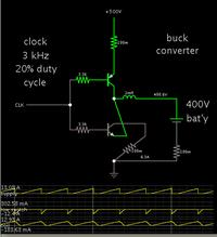
Here is my simulation of a synchronous buck converter.

The supply is 500V, pushing several amps into a 400V battery.


The low switch is an NPN. It is installed upside-down, because it carries current in an upward direction.

The clock oscillator must run at 500V, to turn off the PNP transistor. This may not be easy to achieve. However with some work, it might be possible to use an NPN for the high switch. Then the driving oscillator could run at fewer volts (I think).

The small resistors indicate that there is some amount of resistance in components.
 

Do you have even tried to read some books, applications notes that explains how the buck converter works? Have you tried to look at some on-line classes from those sites that are in the web. For example NPTL? There is lot's of material on-line that you can look at. Try to look for power electronics NPTL, buck-converter, buck-converter losses, etc.

Regards.
 

By the way I made it a synchronous type because your schematic is that type.

You can make this job easier by using a diode for the low switch. It must carry several amps.

- - - Updated - - -

I am still struggling with it. And my supervisor is pretty mad at me- which is not helping me at all..

I hope your supervisor understands the hazard of working with these high voltages.

Do you get the idea your supervisor thinks this is an easy task? It is not. A little coil can work magic for this purpose, nevertheless it still is a big job to get past all the gotcha's.

Including possibility of sparks. Lead-acid types can explode if a spark reaches hydrogen gas inside, or near the vents.

You didn't say what type of battery it is. Each type has its specs as to a safe charge rate.

You didn't state the capacity of the battery. My simulation shows it charging at several amps. However this needs to be reduced if your battery has a small capacity.
 

The transfer function shown in post #3 looks right at first sight. But I think it's more important to know how to control a buck converter in practice than to predict it's behaviour based on assumptions about component parameters that are possibly not corresponding reality.

To setup a current controller, you need a PI or PID controller and a PWM modulator, translating the control signal ("manipulated value") into a PWM duty cyle. I'm not presently using Matlab/Simulink, but it's rather easy to implement both functions with the tool. I also assume that there are many examples available.
 

Not sure how you would do things in simulink, but in real life you need at least one current sensor on the battery or the DC bus, possible both. Then you will use that information to close a current control loop using a PWM controller. Without a current measurement, control will be extremely difficult, probably not feasible at all.

The sensors could be resistive shunt, hall effect, etc.
 

@All: Thank You so much for your help! @Bradtherad I will use a diode fo rthe lower switch - to make things easier..
Once again Thank you all! It is such a relief to know that there are people out there ready to help!!!
 

@All: Thank You so much for your help! @Bradtherad I will use a diode fo rthe lower switch - to make things easier..

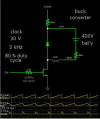
Here is a screenshot of a conventional buck converter (with diode).

I rearranged it so a mosfet switch is at the low side.

That way the simulation can show it being biased with 30V pulses. Being a simulation it doesn't guarantee identical performance with real hardware.

- - - Updated - - -


Hi newbie28,

I am also struggling with a bidirectional DC-DC Converter (in order to charge and discharge the storage battery) in my project.
(you could take a look in the following link if you wish)
https://www.edaboard.com/threads/279800/

I am also using Matlab/Simulink for my simulations and after a lot of searching i have found a simulink model of a HEV, which is attached below (the first one). This model is fully functional and the DC-DC converter used for charging the battery in this model might be what you need for your project. The attached .rar file contains two .mdl files which are simulink models (for charging and discharging) of a bidirectional DC-DC converter i developed myself. It is functional but incomplete. The real problem is that i am not able to develop a proper circuit in order to control the power flow (i.e., when the converter will be in charging and when in discharging mode).

You asked for help on 23-10-12, so i assume that you have hopefully completed your project until now. But if not, i would be happy to help you just a little bit by sending these simulink models.

Best regards,
strkar

- - - Updated - - -

Hi newbie28,

I am also struggling with a bidirectional DC-DC Converter (in order to charge and discharge the storage battery) in my project.
(you could take a look in the following link if you wish)
https://www.edaboard.com/threads/279800/

I am also using Matlab/Simulink for my simulations and after a lot of searching i have found a simulink model of a HEV, which is attached below (the first one). This model is fully functional and the DC-DC converter used for charging the battery in this model might be what you need for your project. The attached .rar file contains two .mdl files which are simulink models (for charging and discharging) of a bidirectional DC-DC converter i developed myself. It is functional but incomplete. The real problem is that i am not able to develop a proper circuit in order to control the power flow (i.e., when the converter will be in charging and when in discharging mode).

You asked for help on 23-10-12, so i assume that you have hopefully completed your project until now. But if not, i would be happy to help you just a little bit by sending these simulink models.

Best regards,
strkar
 

Attachments

  • power_HEV_powertrain.zip
    237.9 KB · Views: 94
  • DC-DC Converter.rar
    25.7 KB · Views: 96

Status
Not open for further replies.

Similar threads

Part and Inventory Search

Welcome to EDABoard.com

Sponsor

Back
Top