Continue to Site

Welcome to EDAboard.com

Welcome to our site! EDAboard.com is an international Electronics Discussion Forum focused on EDA software, circuits, schematics, books, theory, papers, asic, pld, 8051, DSP, Network, RF, Analog Design, PCB, Service Manuals... and a whole lot more! To participate you need to register. Registration is free. Click here to register now.

questions about AD Converter

Status
Not open for further replies.

zhengchao201105

Member level 2
Joined
Jul 11, 2012
Messages
49
Helped
2
Reputation
4
Reaction score
2
Trophy points
1,288
Activity points
1,621
AD_converter.png
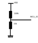
if VBD is 16v,the mcu IO will get a 16v*33k/(33k+100k)=3.96v,this is a good value for a 5v powered MCU
but if change VBD to 26v,the mcu IO will get a 26v*33k/(33k+100k)=6.45V,in this case,does the mcu can still get a 5v input(the mcu will think the external power is 5v/33k*(100k+33k)=20.1V)?or the mcu IO will get a low level even damaged?

I'm not sure I understand your question.

If you asking whether or not the MCU can safely operate with a 6.45V input to an ADC channel, when the devices maximum operating voltage is 5v, the answer is typically no.

And yes it could possibly damage the device.

Another issue I should mention is a relatively large resistance voltage divider can easily exceed the rated source output impedance of the MCU's ADC module.

Typically, the ADC module of a MCU specifies a maximum source output impedance in the 10kΩ range, sometimes less.

A more viable option would be to implement an OPAMP scaler or utilize a OPAMP voltage follower between the voltage divider and the MCU's ADC input.


BigDog
 
thank you for your info,and I understand what you said
what I thought is if the mcu don't read the value,the IO may be not damaged,because there is a 100k resistor in series with 26v,so little current.
 

Using high resistor values will give you wrong results due to the slow charge rate of the S&H capacitor but if the signal you measure is not a rapidly changing one you can use a capacitor at the ADC input that can act as a reserve and present a low impedance to the ADC input

It is also a good idea to use Schottky diodes to protect the inputs

www.cirrus.com/en/pubs/appNote/an20.pdf
https://www.edaboard.com/threads/31010/
 
you will not give micro controller input exceed 5V.

- - - Updated - - -

then that mcu will heat on IC. mcu will damage
 

thank you all guys,even I am not very sure why should add a capacitor paralized with the resistor,but it is true
 

The capacitor is not a requirement and will slow down the rate that the input signal changes (due to the RC) but when you use high value resistors the cap can help because it will charge the S&H cap immediately, the current will not have to go through the resistors so once the cap is charged the voltage will be immediately reflected to the ADC with a very small impedance.
 

what is the S&H cap?why should reflected to the ADC with a very small impedance?
may be I missed some basic knowledge
 

The ADC conversion has two stages , in the first stage a Sample & Hold capacitor charges with the signal that is to be measured , in the second stage the capacitor is isolated from the input and the AD converts the stored voltage of the capacitor to a digital value.

https://en.wikipedia.org/wiki/Sample_and_hold

- - - Updated - - -

Here is the AD input for an AVR mcu

m8_ADC_input.gif

S&H takes 1.5 clocks and then then conversion takes 11.5 clocks

m8_ADC_timing.gif

If the S&H is not charged at the input voltage at 1.5 clocks then the result will be wrong, that is why there is an input resistance recommendation.
 
Status
Not open for further replies.

Part and Inventory Search

Welcome to EDABoard.com

Sponsor

Back
Top