engrMunna
Advanced Member level 4
Hi,
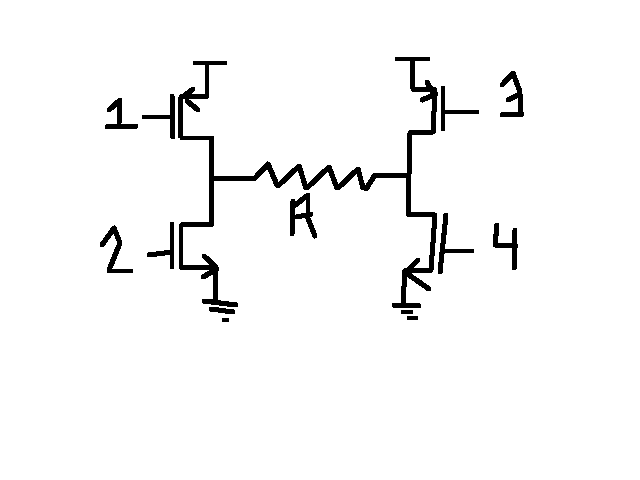
Referring to the figure, the transistors can turn on only in pairs that is either 1 and 4 are on or 2 and 3 are on. So this circuit is an H-Bridge for the R load. And the polarity of the voltage across R is determined by which pair of transistors is on. Now the problem is that R is very low about 200 ohms. I have to build this as an integrated circuit, and I don't want to use large transistor sizes (width of the transistor). Suppose my Supply is of 3 volts and I need a drop of 1 Volt across R, then the channel resistance of Mosfets should be comparable in value with R. And for a channel resistance of around 200 ohms for MOS in 180nm Technology, the transistors have to be unreasonably large. Also for a drop of 1 volt across R, I need a current of 1/200 amps. so for integrated circuits in 180nm this is not reasonable. Can some one suggest an alternative circuit for doing this? A person told me to think about using Current Starved Voltage sources...I don't know how they will help in this case, because for a drop of 1V across a 200 ohm resistance you need definetly need 1/200 amps? I mean this is not possible that you get 1V across R and have a current less than 1/200 amps flowing through R?
Thanks