Continue to Site

Welcome to EDAboard.com

Welcome to our site! EDAboard.com is an international Electronics Discussion Forum focused on EDA software, circuits, schematics, books, theory, papers, asic, pld, 8051, DSP, Network, RF, Analog Design, PCB, Service Manuals... and a whole lot more! To participate you need to register. Registration is free. Click here to register now.

making dc power supply for dc to dc

Status
Not open for further replies.

birenparekh

Newbie level 5
Joined
Oct 8, 2012
Messages
8
Helped
0
Reputation
0
Reaction score
0
Trophy points
1,281
Activity points
1,331
hello all


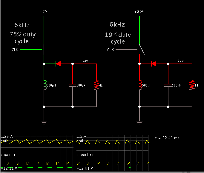
i want to make dc power supply for twelve volt dc output form input of five to twenty volt dc...

so what is the circuit diagram for it.if any source?\
please reply me..
 
Last edited:

A buckboost converter will do what you want.

It inverts the supply polarity, so you'll need to orient your project to be compatible.

Your control circuit will need to detect volt level to the load, and adjust duty cycle accordingly.

To show that the same components can provide 12V output, for a range of input between 5V and 20V, here is a screenshot of my simulation. (I made the control signal a simple clock, for ease of creating this layout.)


thanks ,but i want to make both circuit in one project..so how can it implemented?
 

My diagram shows the same circuit as it would operate with a 5V supply (left) and a 20V supply (right).

It is a simplified demonstration to show that what you wish is possible.

It would need a mosfet or transistor as a switching device. It would need a control IC to apply the switching signal.

There are control IC's which detect the volt level at the load, and which alter the duty cycle of the switching device to maintain a desired volt level.

I have not used such IC's so I don't know specifically what to recommend.
 

thanks,
but i havenot clear the concept of duty cycle.....please can you explain?and which software is used to work on circuit design?
 

thanks,
but i havenot clear the concept of duty cycle.....please can you explain?and which software is used to work on circuit design?
Duty cycle(%) =\[\frac{Ton}{T}\] * 100
where Ton = On duration
T=Total period
i.e. in short, duty cycle is the ratio of duration for which the pulse is on(i.e. positive) to total time period which comprises of on duration + off duration.
So, for e.g. when u say 75% duty cycle, 75% of the total time period, the pulse is on.
Common software related to circuit designing are SPICE(u can use PSPICE, I think the student version is free, not sure check it out). Other one is Multisim.
Their tutorials are available on net, so u can start from scratch learning the softwares initially with some basic circuits then going to some practical circuits.


Status
Not open for further replies.

Similar threads

Part and Inventory Search

Welcome to EDABoard.com

Sponsor

Back
Top