Continue to Site

Welcome to EDAboard.com

Welcome to our site! EDAboard.com is an international Electronics Discussion Forum focused on EDA software, circuits, schematics, books, theory, papers, asic, pld, 8051, DSP, Network, RF, Analog Design, PCB, Service Manuals... and a whole lot more! To participate you need to register. Registration is free. Click here to register now.

class A versus push pull capacitor slewing

Status
Not open for further replies.

Junus2012

Advanced Member level 5
Joined
Jan 9, 2012
Messages
1,552
Helped
47
Reputation
98
Reaction score
53
Trophy points
1,328
Location
Italy
Activity points
15,235
Hi all

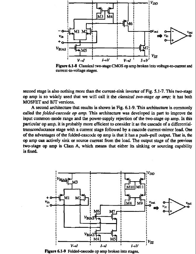
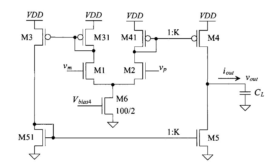
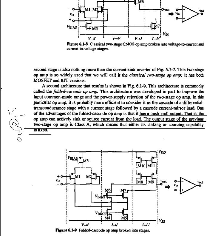
The push pull output stage is supposed to be better than for example class A as it source and sink the capacitor load from both direction, my question is related to the class A , if it can either sink or source ( depending if it is N or P type) then how we are getting a positive S.R that is equal to the Negative S.R ??? mean of how the capacitor are charging or discharging in the other direction ??

I welcome very much your replies
Thank you
 

Push pull defines the arrangement of the output devices, you can have class A push pull. Class A defines that the output device conducts over 360 degrees of the signal input. In the classic single ended amplifier, the transistor will pull the end of the capacitor down to earth, but the collector load must pull it up to 1/2 Vcc (resistor) or Vcc ( choke or transformer).
Frank
 

Thank you Chunkey
Actually the thing that still I am not understanding I marked it with the attached image from Holberg book, again you will see that the class A has either to sink or source that is what I am not getting it, if the op amp is just sinking then how the load being sourced ? and vie versa


Push pull defines the arrangement of the output devices, you can have class A push pull. Class A defines that the output device conducts over 360 degrees of the signal input. In the classic single ended amplifier, the transistor will pull the end of the capacitor down to earth, but the collector load must pull it up to 1/2 Vcc (resistor) or Vcc ( choke or transformer).
Frank
 

The problem isn't clear. You are showing an OTA topology in post #3, it basically "mirrors" the bias current of the input stage into the output node (possibly with a gain factor in the current sources), thus the maximum output current will be symmetrical and meet your intention of symmetrical slew rate with capacitive load.
 

Than kyou Fvm for your participation

I usually designed many two stages op-amp and I already had symmetrical S.R, the thing that whenever I read the marked lines in the page image I attached I dont know what he mean to say, he is saying that the class A which is not working as push pull has only one direction drive capability then by this say I am inquiring how we are getting the symmetrical S.R from this topology which I am already getting ?? hope now it is clear for you

The problem isn't clear. You are showing an OTA topology in post #3, it basically "mirrors" the bias current of the input stage into the output node (possibly with a gain factor in the current sources), thus the maximum output current will be symmetrical and meet your intention of symmetrical slew rate with capacitive load.
 

he is saying that the class A which is not working as push pull has only one direction drive capability
I'm not sure what the text wants to say, unfortunately the part of the schematic, that can tell about the sourcing capability of the said circuit is missing.

Generally, it seems obvious to me that any class A amplifier has sourcing and sinking capability, but not necessarilly symmetrically.
 

Hello FvM

here is the complete image


Thanks.

Different from the symmetrical OTA output current you have Iconst(M7) as maximum sink current and Isat(M6)-Iconst(M7) as maximum source current. Assuming equal transistor sizes, the source current will be usually higher. But you have still source and sink capability.
 
thank you again

your answer helped me, and I am agree with you in this. then if we say this circuit has the both sinking and sourcing then what is the thing making it different from the push and pull according to the author ??

Thanks.

Different from the symmetrical OTA output current you have Iconst(M7) as maximum sink current and Isat(M6)-Iconst(M7) as maximum source current. Assuming equal transistor sizes, the source current will be usually higher. But you have still source and sink capability.
 

In my view, the main difference is that the two-stage amplifier has a higher and nonlinear transconductance.
 

Push pull defines the arrangement of the output devices, you can have class A push pull. Class A defines that the output device conducts over 360 degrees of the signal input.

This appears to be confirmed in a helpful article linked below. It brings out similarities and differences between class A and AB.

**broken link removed**

Portion:

"Another version of the Class-A amp looks exactly the same as a standard Class-AB (Class-B) power amp, except the quiescent current is increased to just over 1/2 of the peak speaker current. This is thought by some (including me up until I was shown the error of my ways) that this is not a "real" Class-A amplifier. It is real Class-A, and is best described as push-pull (as opposed to single ended) operation. If the bias current is not high enough for the actual reactive speaker load (not some quoted nominal resistive load), it is still possible that one transistor or the other will switch off at some part of the signal cycle. This will happen at a much higher power level than is normally the case, but if this happens, then the amplifier ceases to be true Class-A."
 
Ok guys, here is the confusing part , referring to the last post of BradtheRad , me as well many people when we here the push pull it come to our mind the class AB operation where the conduction is less that 360 as for power amplifier.

The circuit in my first post is also called push pull but it conduct for 360, then it mean class A operation, it is a little strange for me to hear push pull working class A

I also attached you more clear image for further discussion,


Obviously the circuits discussed in this thread have nothing to do with class AB.

The term push-pull has been introduced in the quoted literature. I agree that it's not particularly helpful to explain the differences between the two circuits. In my understanding, the author wants to describe that both high and low side are actively driven, in constrast to an outputs stage with a current source load. That's true, but it's not the specific point when comparing the circuits, see post #11.
 
Last edited:

Now it became more clear for me, with the help of post #9 by FvM, and the post of BradtheRad I can say that:

for the two stage op-amp (first image) the sink transistor is working for 360 and never goes off, when the output is positively slewing the capacitor the current will be I6ss-I7ss and when the load is negatively slewing the capacitor the current will be I7. this result that transistor M7 is on for all the cycle of operation then it is class A.

in the second circuit (from post #13 more clear) the transistor M4 is sourcing the capacitor during the positive slewing and as the current in M4 increase as the current in M5 decrease,at the end M5 will be completely off and M4 will source the all current. the reverse will happen with the negative slewing . so one is pushing other is pulling (push pull)

I think as a result the second circuit is more power efficient , for my view of opinion , the circuit is also AB as the other transistor will be off at the end of the next cycle
 
Last edited:

I agree to the description. I think, you understand now the basic difference regarding current variation of the output stage.
 

Thank you FvM, Thank you all guys for your helpful participation , see you with other posts
 

Status
Not open for further replies.

Part and Inventory Search

Welcome to EDABoard.com

Sponsor

Back
Top