Continue to Site

Welcome to EDAboard.com

Welcome to our site! EDAboard.com is an international Electronics Discussion Forum focused on EDA software, circuits, schematics, books, theory, papers, asic, pld, 8051, DSP, Network, RF, Analog Design, PCB, Service Manuals... and a whole lot more! To participate you need to register. Registration is free. Click here to register now.

Problem Identifying the Light / IR detector

Status
Not open for further replies.

ark5230

Advanced Member level 3
Joined
Jun 29, 2009
Messages
862
Helped
163
Reputation
324
Reaction score
140
Trophy points
1,323
Location
India
Activity points
6,187
I am using a heart rate monitor that makes use of LED as source of light and claims of using an IR detector.
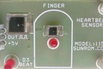
The module is from sunrom.com as shown in the attached figure. The rectangular component is said to be IR detector as per Sunrom description. May be the LED that is emitting RED light has some component of IR radiation or the detector may be broad band sensitivity. I am trying to figure out what type of detector it is that I am unable to identify. If some body could identify the type of detector it will be of help to me. HR_detector4.jpg
 

A pulse oximeter works by sending two beams of different wavelengths. The thing above the Led could be an IR led. The sensor will recieve both to pick the pulse waveform and calculate saturation and the pulse rate.
Texas instruments have suitable sensors.
However your application may be simpler and may require just one wavelength.
 
True, the application is not critical, I am using it without knowing what exactly it is. It gives pulse rate. There is circuitry behind the PCB with microcontroller. The surface of the sensor is flat and two electrode connections are also visible so the question that is it LED sort of thing or something else !!
 

Yes, True it is something like this. Actually I wanted to do some experiment with this to improve its performance the way I need. If I could know the type of component and the sensor type, it would be easier. Now I think if some other light (red) or IR detector can be used with suitable pulse shaping and signal conditioning circuitry. My curiosity increased reading the information supplied by the component provider sunrom.com which says it is IR sensor where as the light source used is bright RED LED. I thought they could have used IR LED and IR detector or RED light detector with RED LED.
 

I reviewed the product description and datasheet at sunrom.com and didn't find the term "IR detector" mentioned in a single place. Where did you see it? The datasheet describes it as a "light detector". The photo seems to show a standard photo diode similar to BPW34.
 
Hello!

I think you shouldn't try to mess with separated diode and sensor. There are many devices doing
what you want, why reinvent the wheel? I have made one some time ago with TCRT1000 (see
the links provided by Bigdog (Easy pulse). But you can do something smaller. A lot smaller by
using op-amps.
Note that the problem with this method is that you have to power the diode permanently.
As the low and high pass filters' order of magnitude is around 1 Hz, then you have to switch the
LED on at least a few seconds before performing your measurement so that the signal has time
to stabilize. Basically you cannot switch it off if you want a continuous measurement. And since
the signal's level AC part is small, it's difficult to do it digitally.

Dora.
 
Thank you very much FVM, I checked the datasheet under reference, it does not claim IR at any place. I think I mixed information from somewhere and was confused about that. I will figure out where from the IR issue cropped in. Thanks again form resolving the confusion at my end. I will also see the diode described in your post 6.

- - - Updated - - -
I checked the data sheet of BPW34 diode. It shows that the sensitivity peaks at around 900 nm which is in IR region, may be due to this reason some related literature referred to this (or similar) diode as IR detector. Thanks again to all.
 

Yes this seems to be a better option compared to crude isolated source and detector pair as shown in Post #1.
The Figure shown in Post #1 has a detailed circuitry including PIC micro controller and few other IC's all SMD. I will try to see if a better design could be evolved. There is problem with that shown in Post #1. It gives pulses under control of the PIC microcontroller where the time increment is in unit of 10 ms. Better resolution is better.
 

Status
Not open for further replies.

Similar threads

Part and Inventory Search

Welcome to EDABoard.com

Sponsor

Back
Top