shan_ahmed
Newbie level 4
Hello everyone, i want a 16 pins lcd in proteus, where to slect it? model nmbr?? Please
Follow along with the video below to see how to install our site as a web app on your home screen.
Note: This feature may not be available in some browsers.

Code C - [expand]
Use a 14 pin lcd instead.
How to do that?? wot to do with remaining 2 pins??
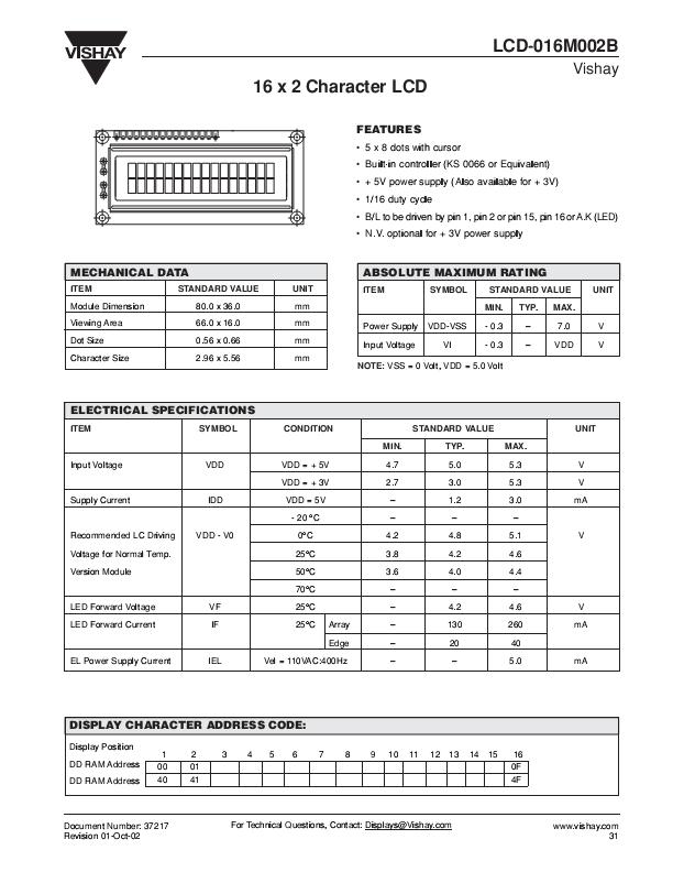
If the LCD is HD44780 compatible the remaining two pins are for a backlight, pins 15 and 16 in the schematic you'll uploaded, which are certainly not a requirement for a successful simulation.
Simply leave them disconnected.
BigDog
16 pin LCD 16 pin Proteus design file and PCB footprint
more PCB Footprints:
https://www.edaboard.com/threads/257982/