Continue to Site

Welcome to EDAboard.com

Welcome to our site! EDAboard.com is an international Electronics Discussion Forum focused on EDA software, circuits, schematics, books, theory, papers, asic, pld, 8051, DSP, Network, RF, Analog Design, PCB, Service Manuals... and a whole lot more! To participate you need to register. Registration is free. Click here to register now.

[SOLVED] Help with shortcut protection circuit

Status
Not open for further replies.

mariuszoll

Member level 5
Joined
Aug 28, 2012
Messages
82
Helped
1
Reputation
2
Reaction score
0
Trophy points
1,286
Activity points
2,147
Hi,

I have to implement a shortcut protection in my project.
Can somebody give me some ideas in order to know how to make it.

Thank you in advance.
 

What do you mean by "shortcut protection"? Do you mean short-circuit protection?

What is the supply voltage? There are many ways to achieve the short-circuit protection, such as crow-bar protection with thyristor, or MOSFET-based on/off control based, etc.
 

Yes, I mean short-circuit protection. The supply is between 9V and 16V.
I have just found an IC from ST, but unfortunately it is too expensive. I know that in general, ICs are more expensive than circuits made with discrete components. Could you please show me a short circuit protection made with discrete components?

Thank you
 

One circuit you could use is:

Sense the current flowing through (a shunt may be used, or you can use any other type of current measurement device). Compare the value against a preset value. If the measured current < reference current, switch on a MOSFET that permits current flow through the load. Keep on sensing the current. If the current > reference value, turn the MOSFET off and keep it latched off. Then, you could add a "manual reset" feature to reset the circuit (like a circuit breaker), or you could just remove power and connect again.

Hope this helps.
Tahmid.
 
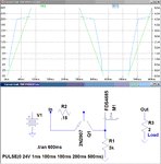
Here is a current limit circuit that uses a bipolar transistor and a MOSFET, and has a maximum voltage drop of about 0.7V (not including the MOSFET resistance) at the limit. The current limit is approximately equal to 0.7V divided by R2. The MOSFET must have the current and power capacity to carry the limit current. The duration of the limit, the value of the limit, and the value of the supply voltage determines the size of the MOSFET heat sink required.

Current Limit 2.gif
 
Last edited:

Hi crutschow,

Thank you for the reply. Could you tell me please how did you choose the value of resistor R1 (3K).

Thank you

- - - Updated - - -

One circuit you could use is:

Sense the current flowing through (a shunt may be used, or you can use any other type of current measurement device). Compare the value against a preset value. If the measured current < reference current, switch on a MOSFET that permits current flow through the load. Keep on sensing the current. If the current > reference value, turn the MOSFET off and keep it latched off. Then, you could add a "manual reset" feature to reset the circuit (like a circuit breaker), or you could just remove power and connect again.

Hope this helps.
Tahmid.

Thank you Tahmid for reply.
I guess that for current measurement I need some ICs. The problem is that I want to do it just with discrete components.

Thank you.
 

    V

    Points: 2
    Helpful Answer Positive Rating
Thank you Tahmid for reply.
I guess that for current measurement I need some ICs. The problem is that I want to do it just with discrete components.

Thank you.

What I meant was that, you could design a circuit using common simple ICs (eg. opamps / comparators) instead of dedicated chips. So, cost is reduced and you use ready-made available components.
 

Do you know any possibilities to turn off the M1 mosfet when Iload becomes larger than Vbe/Rsens?
I would prefer an idea without ICs.

Thank you.
 

Do you know any possibilities to turn off the M1 mosfet when Iload becomes larger than Vbe/Rsens?
I would prefer an idea without ICs.

Use foldback current limiting. For a generic circuit suggestion, see e.g. here (scroll down).

A better explanation (in Spanish) including resistor calculation is given here (scroll down to protección contra sobrecarga).

You can find more circuit suggestions via G00gle images.
 

Status
Not open for further replies.

Part and Inventory Search

Welcome to EDABoard.com

Sponsor

Back
Top