Continue to Site

Welcome to EDAboard.com

Welcome to our site! EDAboard.com is an international Electronics Discussion Forum focused on EDA software, circuits, schematics, books, theory, papers, asic, pld, 8051, DSP, Network, RF, Analog Design, PCB, Service Manuals... and a whole lot more! To participate you need to register. Registration is free. Click here to register now.

2khz frequency noise

Status
Not open for further replies.

denver56

Member level 3
Joined
Mar 18, 2012
Messages
67
Helped
0
Reputation
0
Reaction score
0
Trophy points
1,286
Activity points
1,725
Hi people !
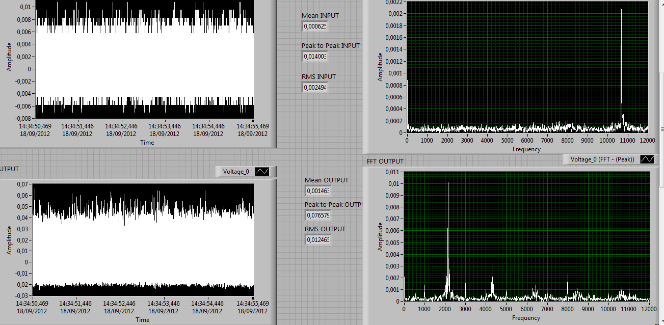
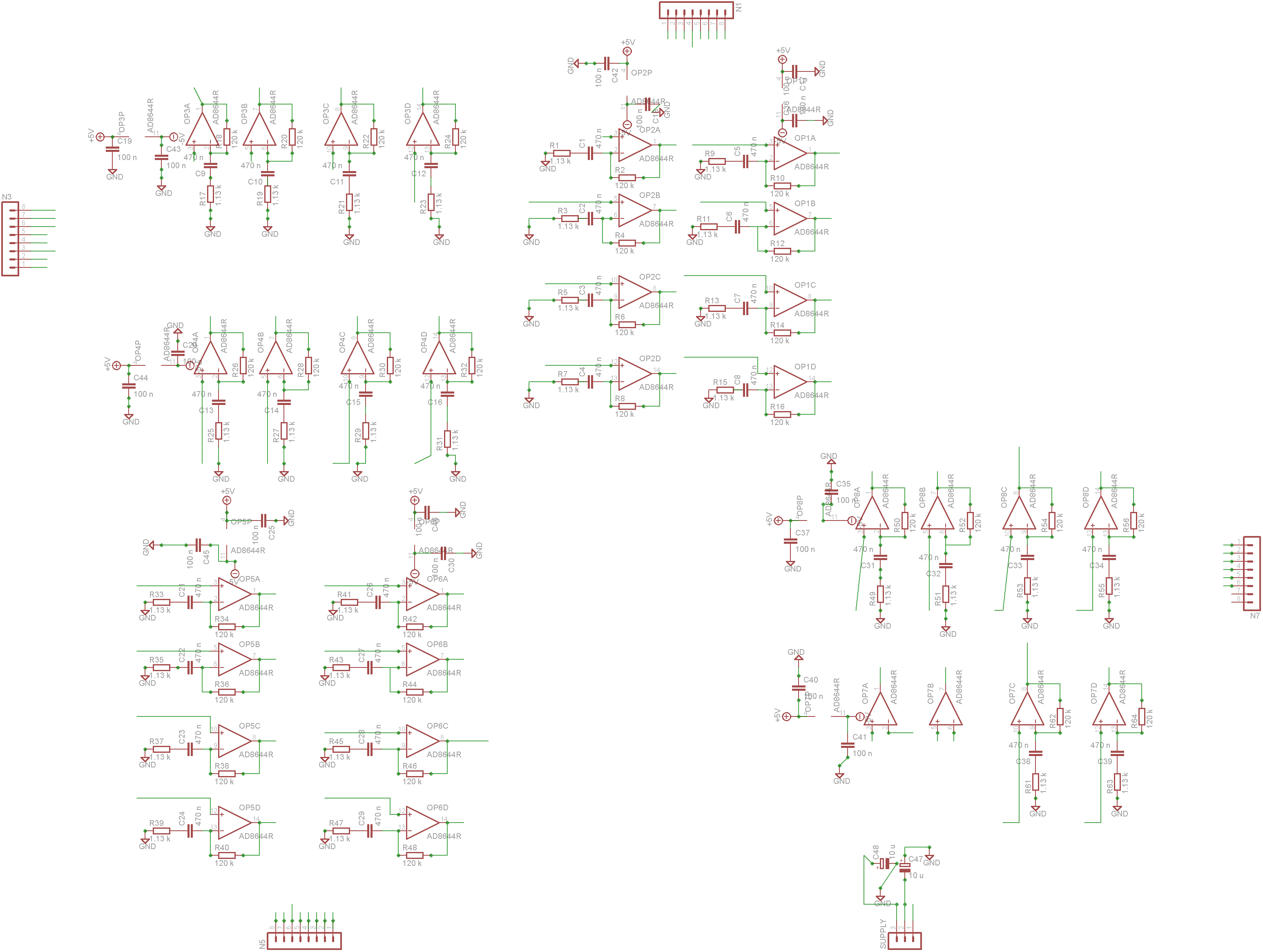
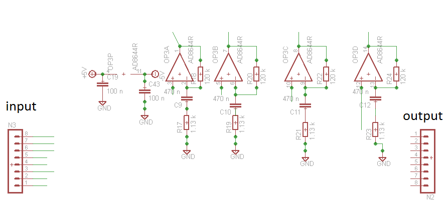
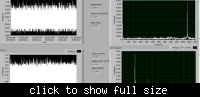
I am doing some input-referred noise tests on a Pcb. This Pcb is composed by 8 quad-op amp that filter and give gain to signals. Actually I made this test also on his twin boards and I didn't notice frequency noise. Instead in this Pcb there's a big noise at ouptut at 2Khz frequency even when the signal input is linked to the ground (see the attachment). I give supply to the board with a laboratory dc power supply (7 Volt) and obviously there are 2 electrolytic capacitors on the board. Anyone has some idea to how reduce this noise?
Thank you very much!


The 10.5 kHz line, although lower level doesn't look much better.

I know this is a multi-channel design. It would be reasonable to identify where the signal is actually generated. Although some people use "noise" in very broad sense, I won't use the term in the present case. The signal looks more like generated by self-oscillation, but not in the channel you are presently probing.

I presume that some kind of wiring error or wrongly placed component value will cause the interference by turning part of your circuit into an oscillator. If all filters have different frequency, it may be a design fault as well.
 
the working has been modified a little too much due to some errors in design post the schematic of the ckt that can help us a lot in identifying the issue
 
If one board works and the other doesn't, then there appears to be an error on the one board causing an oscillation. One likely error is an incorrect component value somewhere on the board. If you can isolate the source of the oscillation, that will reduce the components that you need to check.
 
well, in the tested twin board two resistor of the non-inverter op-amp were mistaken in two channels. In that board the 2khz noise exist but it's lower.
Here the schematic! Thank you very much
 

Attachments

  • PCB 1_guardie.zip
    62.4 KB · Views: 65

How about gain margin/phase margin in your amplifiers? Most likely, they are oscillating. (Obs.: can't read *.sch file. Jpg?).
 
this is the datsheet of opamp:
**broken link removed**

Here the jpeg
 

A potential problem is brought up by floating OP inputs. You need to terminate all inputs either to ground or a signal source.
 
do you think that shielding the circuit will avoid this 2khz noise ?
Gain margin : see the attachment
I don't know the fase margin but when I simulated it shouldn't exist resonance peak in the closed loop... Do you know how to calculate it from the schematic?
THX


Your analysis is correct. There should be absolutely no stability problems according to the implemented filter function. Particularly there's no reason for a 2 kHz resonance.
 

yes. Here is the exemplum of one quad-op amp. What do you think ? Also you think there may be the presence of parassitic capacitor ?
THX

2734414700_1348649959.png


Status
Not open for further replies.

Similar threads

Part and Inventory Search

Welcome to EDABoard.com

Sponsor

Back
Top