Welcome to our site! EDAboard.com is an international Electronics Discussion Forum focused on EDA software, circuits, schematics, books, theory, papers, asic, pld, 8051, DSP, Network, RF, Analog Design, PCB, Service Manuals... and a whole lot more! To participate you need to register. Registration is free. Click here to register now.
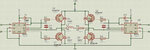
i got the attached circuit dig. from another thread in this forum. i just ned to know wat is the input given to the hin and lin pin of the ir2112.
please i have no idea wat should be the input and i need to know about it fast.
HIN Logic input for high side gate driver output (HO), in phase
LIN Logic input for low side gate driver output (LO), in phase
Logic inputs are compatible with standard CMOS or LSTTL outputs, down to 3.3V logic.
A high signal to the HIN pin drives the high-side MOSFET on. A low signal drives it off.
A high signal to the LIN pin drives the low-side MOSFET on. A low signal drives it off.
You can not keep the high-side MOSFET on for more than a specified amount of time, dictated by the size of the bootstrap capacitor.
You would want to generate pulses to alternately drive the high-side and low-side MOSFETs. Make sure you have a small "dead-time" to avoid cross-conduction between high and low side MOSFETs (which would just create a short-circuit).
i need to ask one more question..
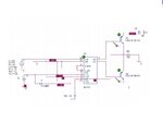
i have to simulate this circuit in Pspice so should i use Vpulse to give pulses to HIN and make LIN grounded or should i do something else??
thanks a lot.. i have very less idea about IR2112..
- - - Updated - - -
i have made the attached circuit in pspice but not getting the output can u please tell wat is the mistake..
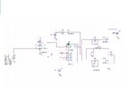
This is another circuit with flip flop and i am getting the following error
Model IO_AC used by X-U5A, Uff11 is undefined0.
what does this error means?
and how to solve it.
This is another circuit with flip flop and i am getting the following error
Model IO_AC used by X-U5A, Uff11 is undefined0.
what does this error means?
and how to solve it.
i got the attached circuit dig. from another thread in this forum. i just ned to know wat is the input given to the hin and lin pin of the ir2112.
please i have no idea wat should be the input and i need to know about it fast.[/QUOTE
plz in order to simulate the circuit you drawn here,loop the two lins and two hins pins of ir2110 together,then give them two oscillator signals from pwm generator like sg3524.you also need to insert a center tapped iron core transformer lying in library instead of of l2 and try to simulate the cct.
I have simulated so many ccts. like this,regards
salam;
in ic(u2) the hin (pin10) of ic is the controll of q2 and similarly lin (pin12)is the controll pin of q3
you can switch on the q2 by applying 8v to 15v on pin hin and switch of q2 by applying 0v on this pin
similarly lin is the controll of q3
same theory apply on ic1
This site uses cookies to help personalise content, tailor your experience and to keep you logged in if you register.
By continuing to use this site, you are consenting to our use of cookies.
")