Continue to Site

Welcome to EDAboard.com

Welcome to our site! EDAboard.com is an international Electronics Discussion Forum focused on EDA software, circuits, schematics, books, theory, papers, asic, pld, 8051, DSP, Network, RF, Analog Design, PCB, Service Manuals... and a whole lot more! To participate you need to register. Registration is free. Click here to register now.

Error CST: The calculation seems to be unstable! A possible source of instability....

Status
Not open for further replies.

leesixan

Junior Member level 1
Joined
Apr 21, 2012
Messages
19
Helped
5
Reputation
10
Reaction score
5
Trophy points
1,283
Activity points
1,401
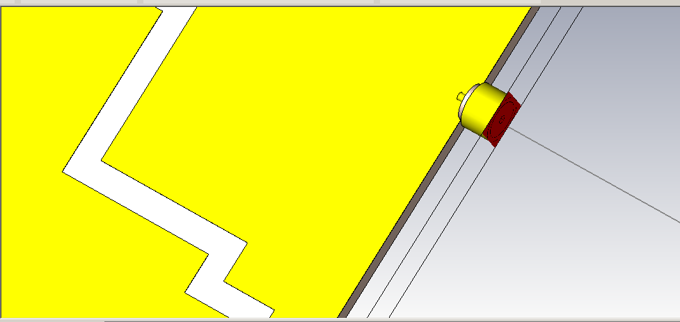
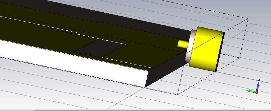
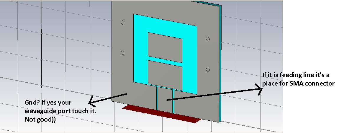
I have problem with CST 2010. I met error: "The calculation seems to be unstable! A possible source of instability could be given by inaccurate definition of internal waveguide ports. Please consider to increase the dimension or shield your waveguide port"-attach file error CST.jpg. I search Google and this forum, but i dont find solution.
What's the reason for this?
please help me if you know
Thanks for read thread.
 

Can you be a little more specific about your project? What are you simulating? If it planar (microstrip for example) the rules for defining size of waveguide port exist (depend on substrate height & microstrip width). Additonally for planar projects i usually simulate SMA connectors to connect to lines (after it i added waveguide port to SMA - solves to me all problems with definition of size)
 
Can you be a little more specific about your project? What are you simulating? If it planar (microstrip for example) the rules for defining size of waveguide port exist (depend on substrate height & microstrip width). Additonally for planar projects i usually simulate SMA connectors to connect to lines (after it i added waveguide port to SMA - solves to me all problems with definition of size)
I am simulating CPW+CLRH_TL. My Design in attach file. I hope it useful.View attachment zor antenna.zip
Thanks for reply my topic.
 

Your port seems to more too large - it touches three or two different lines. I'll see it more thoroughly when i'll have more free time. For a while look at attached pictures it can help you. My advice build SMA connector (it takes time) or use discrete port
 
Your port seems to more too large - it touches three or two different lines. I'll see it more thoroughly when i'll have more free time. For a while look at attached pictures it can help you. My advice build SMA connector (it takes time) or use discrete port
I think my port is large, too. But if this dimension is smaller => error come faster. I'm begineer. Have u any sample built by CST?
 
  • Like
Reactions: amntt

    amntt

    Points: 2
    Helpful Answer Positive Rating
Sorry for late response. Attached example project with SMA connector
 

Attachments

  • line2.rar
    13.6 KB · Views: 224
Sorry for late response. Attached example project with SMA connector
Yes. It's GND. But i don't understand why not good? I set port like a tutorial of CST and HFSS (attach file).
I can't open your file. Have error Snap15.png. I'm using CST 2010. And you?
Thanks you very much for your help.
 

Attachments

  • port_tutorial_cpw_9984.pdf
    544.5 KB · Views: 815
Last edited:
  • Like
Reactions: amntt

    amntt

    Points: 2
    Helpful Answer Positive Rating
I use 2011 ((
Additional question (i don't understand antennas, but it seems to me that your feeding line is not connected to other parts of antenna, is it suppose to be that way?)
About the port may be you are right but logically doesn't seems to me. Anyway try SMA connector you have nothing to loose. I can do it but it will take for me month to do it (unfortunately i haven't much time at all) so if you want just tell me..
 
  • Like
Reactions: leesixan

    leesixan

    Points: 2
    Helpful Answer Positive Rating
    V

    Points: 2
    Helpful Answer Positive Rating
I use 2011 ((
Additional question (i don't understand antennas, but it seems to me that your feeding line is not connected to other parts of antenna, is it suppose to be that way?)
About the port may be you are right but logically doesn't seems to me. Anyway try SMA connector you have nothing to loose. I can do it but it will take for me month to do it (unfortunately i haven't much time at all) so if you want just tell me..
i will try sma connector. But i can't open your example and i dont have datasheet of sma connector to simulation. I want to do it my self. After 1 week, if i can't do it, please help me :)
 

I use 2011 ((
Additional question (i don't understand antennas, but it seems to me that your feeding line is not connected to other parts of antenna, is it suppose to be that way?)
About the port may be you are right but logically doesn't seems to me. Anyway try SMA connector you have nothing to loose. I can do it but it will take for me month to do it (unfortunately i haven't much time at all) so if you want just tell me..
I dont know dimension of sma connector. Then i choose random :). I dont know my design is true or wrong :(. Can u check it for me? Thanks so much for your help
 

Attachments

  • ZOR-an.zip
    17 KB · Views: 169
  • Like
Reactions: amntt

    amntt

    Points: 2
    Helpful Answer Positive Rating
I'll check it but unfortunately you must be patient cause it will take time for me.
SMA dimensions: I usually use AppCad/Passive components/Round Coax for calculating dimensions - Zo of connector is 50ohm)). Dielectric and dimensions can be different from real life connector, more important for me characteristic impedance.
I design dimension depending on my substrate: external metal of connector(its ground) must have the same -Z coordinate (at minimum) as ground.
 
In order to calculate the maximal stable timestep, MWS uses a certain method. This will
give you a stable timestep in 99.9% of all cases. In some cases it fails to give you the
correct timestep. In this cases you have to reduce the timestep till the calculation get
stable. I would start with a factor of 0.9, if it still is unstable go to 0.8 and so on.
http://www.cst-korea.co.kr/Application/CST_MWS.pdf
 
  • Like
Reactions: amntt

    amntt

    Points: 2
    Helpful Answer Positive Rating
In order to calculate the maximal stable timestep, MWS uses a certain method. This will
give you a stable timestep in 99.9% of all cases. In some cases it fails to give you the
correct timestep. In this cases you have to reduce the timestep till the calculation get
stable. I would start with a factor of 0.9, if it still is unstable go to 0.8 and so on.
http://www.cst-korea.co.kr/Application/CST_MWS.pdf

how many time we have permission to do this? for example until 0.5 or 0.4 ?
 

i also sometimes faced same problem.but this has been solved when i increase the dimension. But why i don't know? Could you please why this problem i faced and why it is being solved after increasing the dimension?

I have another problem regarding antenna design by CST. I can't add inclined slot on patch since i don't know how to add this. I can add straight slot. And what is the appropriate method to excite feed line by discrete port and waveguide port?
 

Status
Not open for further replies.

Part and Inventory Search

Welcome to EDABoard.com

Sponsor

Back
Top