adnan012
Advanced Member level 1
hi,
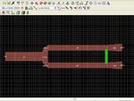
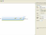
i have problem with the simulation of Wilkinson splitter at 1847MHz. I can't set TFR properly in ADS momentum. Schematic Simulation works well with lumped 100ohm resistor. But i cant get same result in Momentum. How can i set TFR sheet and at which location it must be placed.
I am following the 2nd design on this page.
**broken link removed**