Continue to Site

Welcome to EDAboard.com

Welcome to our site! EDAboard.com is an international Electronics Discussion Forum focused on EDA software, circuits, schematics, books, theory, papers, asic, pld, 8051, DSP, Network, RF, Analog Design, PCB, Service Manuals... and a whole lot more! To participate you need to register. Registration is free. Click here to register now.

audio current limit protection circuit

Status
Not open for further replies.

zhengchao201105

Member level 2
Joined
Jul 11, 2012
Messages
49
Helped
2
Reputation
4
Reaction score
2
Trophy points
1,288
Activity points
1,621
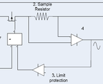
I am making a audio current limit protection circuit.and I got a block which share me some ideas.
you can find the block.
current_limit_LT6100.png
they recommend to use LT6100 for current sensor,I use LTspice to simulate the result and find it is useful to DC but not good for audio signal.
the output is also a sine wave and the amplitude is proportional to the LT6100 supply voltage but not the input sine wave amplitude.
so should I need some special chips to measure the sine current?
the audio signal will connect to a 8ohm speaker ,so I think the current RMS value is big enough in some case.
lLT6100_simulation.pnglt6100_circuit.png
if current value is difficult to detect,so should I choose some voltage limit protection circuit,if I define the current limit value is 4A,so the voltage limit value is 4*8=32v,and the peak to peak value is 32*1.414v=45v?
the sine wave current limit protection is giving me a headache,so hope you can share me your idea?thank you!
 
Last edited:

the LT6100 is designed for current measurements of DC currents - from (say) a power supply, not for Irms measurements of audio signals.
Also your 'schematic' is terrible... too many things missing, and can't really get any useful information from it.

You need an entirely different approach to your problem. Also do remember - what is it that your current protection circuit will do ? Does it shutdown everything ? Or does it attenuate the input signal ? What happens when it detects over-current ?

Whatever you design, please remember that it is easy to get into oscillation mode if you haven't thought about the above points.

cheers!

thank you for your info
this schematic is from the datasheet in the first page,may be something missed because I don't read the datasheet totally.
I will use the limit value to shut down the PMOS.
audio_test_circuit.png
 

I'm missing a general point, what do you want to achieve exactly with your protection circuit?

Audio amplifiers have often internal current limiting to protect against output shorts, also often thermal protection. They won't need additional protection.

If you possibly want to protect speakers, the situation is quite different:
- speakers should be primarly protected against average input power, they have no problem to handle short bursts
- tweeters in multi-band speaker systems have considerable lower power rating. They are particularly sensitive to distorted waveforms generated by overloaded amplifiers
- to protect speakers against overload, you rather want to limit average power by an automatic level control cicruit than cutting instantaneous current or voltage
 

this test instrument will be used to test the speaker,add a external sound source to the speaker.
I will confirm about why a current limit circuit is need in this block.
I guess in some case the external sound source is large enough to burn down the speaker
the whole system is convert the sine wave to square wave and square will be sent to MCU for frequency count,and convert sine wave amplitude to "virtual value" and send this value to the mcu AD convertor
 

A "hard" current limit will generate distorted waveforms that are supposed to damage speakers, particularly tweeters. You won't want to implement in a test system or a regular audio amplifier. An ALC-like soft limiting would be appropriate.

For the current or voltage measurement an averaging RMS detector would be preferable. If you don't know how to build it you can refer to ICs from Analog or TI.
 
I wanna use AD637 as the AC to RMS convertor,hope it is helpful
 

Status
Not open for further replies.

Similar threads

Part and Inventory Search

Welcome to EDABoard.com

Sponsor

Back
Top