Continue to Site

Welcome to EDAboard.com

Welcome to our site! EDAboard.com is an international Electronics Discussion Forum focused on EDA software, circuits, schematics, books, theory, papers, asic, pld, 8051, DSP, Network, RF, Analog Design, PCB, Service Manuals... and a whole lot more! To participate you need to register. Registration is free. Click here to register now.

What is the function that transistor in the circuit?

Status
Not open for further replies.

samy555

Full Member level 4
Joined
May 11, 2010
Messages
207
Helped
0
Reputation
0
Reaction score
0
Trophy points
1,296
Location
Palestine
Activity points
2,963
Hi

HearingAid-3.gif


I want to know what is the role of the transistor Q3 in the circuit, and why 1N4148 Diode?
I read the following but didnot uvderstand so much:
http://talkingelectronics.com/projects/HearingAid-2/HearingAid-2.html
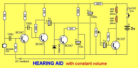
The Hearing aid circuit above is a 3-stage arrangement, using transistors 1, 2 and 4. The third transistor discharges a 10u electrolytic when audio passes through the circuit and is not part of amplifying the signal.
We will concentrate on the operation of the third transistor.
The 10u is initially charged via the 100k resistor and the voltage on the 10u is passed to the base of the first transistor to provide maximum gain.
When audio is passed through the circuit, any waveforms above 0.6v are detected by the third transistor to turn it on briefly. This action partially discharges the 10u via the 1k5 resistor. The lower voltage on the 10u is passed to the first transistor to reduce its gain.
In this way, any loud signals are not amplified as much as weak signal and the circuit will pick up very faint sounds while it will not be overloaded by loud signals.
The output is connected to high-impedance earphones.
thanks
 

hi,

diode 4148 is used as small switching diode. the 3rd transistor is used as switch some small noise in the amplification.
 

they do two things:

1. The two PN junctions (diode and B-E junction) clip the sound level to prevent it becoming too loud.
2. Q3 is unbiased, it gets turned on by the signal being rectified. when it turns on, it's collector voltage drops and the bias to Q1 is reduced, forming a crude automatic gain control.

Brian.
 

I do not understand
What do you mean by "used as small switching diode"?
Please explain more clearly
thanks

- - - Updated - - -

they do two things:

1. The two PN junctions (diode and B-E junction) clip the sound level to prevent it becoming too loud.
2. Q3 is unbiased, it gets turned on by the signal being rectified. when it turns on, it's collector voltage drops and the bias to Q1 is reduced, forming a crude automatic gain control.

Brian.

Great answer
Fully understood
thanks Brian
 

it is necessary for the input of the q3 transistor.

- - - Updated - - -

if you want to remove 1n4148 then you want to remove q3 also.
 

My question is what will happen if left transistor 3 and removed the diode?
 

Ok I'll test it
I have another question:
Why charging the 10u cap through a big 100K resistance (t= 1.1 R C = 1.1 sec) and discharge it through a relatively small 1.5 k resistance (t = 17msec), Why choose those values ​​of resistors?
thanks alot
 

This is a kind of Automatic Gain Control / Automatic Volume Control.

If the Audio signal is strong enough, Q3 will start conducting. This in turn will reduce voltage at its collector and, hence at the base of Q1. So Q1 will have a lower gain. This ensures that the audio level will not get too strong for comfortable listening.

The BE junction of Q3 will limit the audio signal about 0.7Vpeak for positive amplitude. The diode will do the same for negative amplitudes. So, audio level after Q2 is limited to 0.7Vpeak (or 1.4 V peak-to-peak, if you prefer).

Thank you i understand it
I have another question:
Why charging the 10u cap through a big 100K resistance (t= 1.1 R C = 1.1 sec) and discharge it through a relatively small 1.5 k resistance (t = 17msec), Why choose those values ​​of resistors?
thanks alot
 

If the capacitor was omitted altogether the circuit might oscillate. If it is made larger, the response to changes in audio level would be slower. Ideally the voltage across it would follow the envelope of the sound but some compromise has to be made as the envelope might change quickly or slowly depending on the sound being picked up. 10uF/100K are reasonable values to give reasonable results.

Brian.
 

Thank you i understand it
I have another question:
Why charging the 10u cap through a big 100K resistance (t= 1.1 R C = 1.1 sec) and discharge it through a relatively small 1.5 k resistance (t = 17msec), Why choose those values ​​of resistors?
thanks alot

http://www.google.pt/imgres?q=envel...8&start=18&ndsp=24&ved=1t:429,r:17,s:18,i:184

41.png


The circuit acts pretty much like a peak detector, or an envelope demodulator as you can find in an AM radio receiver. Are you familiar with those circuits?

Usually you want the circuit to be fast enough in the presence of a signal, but then decay somewhat slowly as in the figure above. Hence, the different resistors will make different time constants.
 

this configuration provides stable biasing as well as fast correction circuit
the circuit will provide a stable bias during normal operation since the time constant is high
However, once the Q3 is activated the circuit must be fast enough to cut the input as soon as possible
that is why there are two time constants
 

the Diode is used in a negative clamp circuit with Vbe of Q3 as a positive rectifier and gain feedback so that the signal on the base goes from -0.6 to +0.6V p-p. When Q3 conducts, it forces Q1 to attenuate from maximum gain mode with a pull up resistor to pull down. THe large cap slows down the loop response to give fast attack and slow decay.
 

My question is what will happen if left transistor 3 and removed the diode?

the main purpose of using the diode is to trigger the q3 even in negative voltage ip without that there is no use as part of the voice signal will be clipped off
 

not quite jeff
Diode is used in a negative clamp circuit with Vbe of Q3 as a positive rectifier

negative clamp is same as saying DC restoration circuit after AC coupling.. similar to a TV video signal clamping to negative sync or black levels.

so Q3 Vbe Diode is an active positive peak detector used to drive Q1 out of conduction to lower the loop gain... The cap driven by Q3 is fast and in silence decays slower

There is no advantage to using a full bridge clamp instead of a half wave clamp when you use a fairly symmetrical voice envelope to control the gain. (symmetrical within 6dB is close enough) for regulating AGC
 
Status
Not open for further replies.

Part and Inventory Search

Welcome to EDABoard.com

Sponsor

Back
Top