Continue to Site

Welcome to EDAboard.com

Welcome to our site! EDAboard.com is an international Electronics Discussion Forum focused on EDA software, circuits, schematics, books, theory, papers, asic, pld, 8051, DSP, Network, RF, Analog Design, PCB, Service Manuals... and a whole lot more! To participate you need to register. Registration is free. Click here to register now.

Coaxial port setup in Sonnet

Status
Not open for further replies.

stefanpo

Newbie level 4
Joined
May 14, 2012
Messages
5
Helped
1
Reputation
2
Reaction score
1
Trophy points
1,283
Activity points
1,337
Dipole.jpg

Hello all,

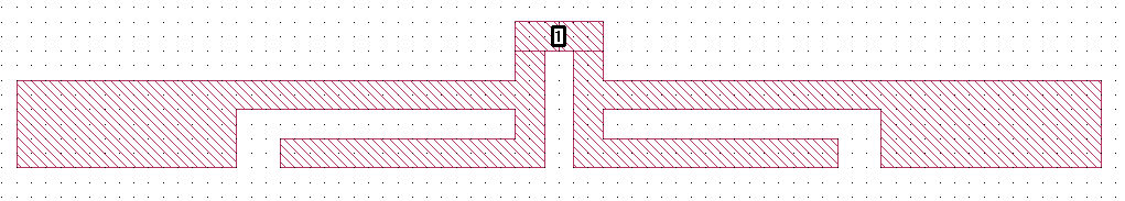
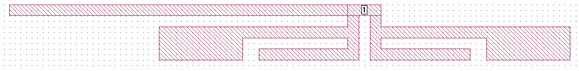
I am trying to simulate the attached antenna in Sonnet. It is a single-side PCB antenna. Metal trace lines are on top of a dielectric substrate (e.g. FR4) and NO metal on the backside of the substrate.

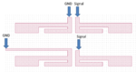
Since the antenna is fed with a coaxial cable, I would like to simulate the same port condition, i.e. one arm is connected to a signal port and the other one is connected to ground. Please note that the two arms are not connected electrically.

Because it is an antenna, I don't want to use wall port which put my antenna too close to the conductive wall affecting the performance. Can anybody suggest how to set up this kind of port in Sonnet?

Many Thanks : )

- - - Updated - - -

to be more specific, I would like to simulate an unbalanced input for an antenna, i.e. one signal one ground. But not a balanced input, i.e. one +ve signal one -ve signal.
Is this kind of difference taken care in simulation software like Sonnet?
 

Try to use an ungrounded internal port:


Switch OFF de-embedding in the simulation settings: Analysis > Setup > Advanced > De-Embed
This is because de-embedding assumes a clear ground return path, which you don't have with free space top and bottom cover.

The internal port is not unbalanced, but the question is: what would an unbalanced port mean? The term (un)balanced refers to some global ground reference. For your antenna, it is not clear to me what that external ground reference would be. If you want to imitate the effect of the ground line in parallel to one antenna arm, maybe you can model that as an additional metal strip connected to one side of the port. This will create the correct coupling with the ground shield, and the antenna excitation will be between the antenna arms. Should be correct in my opinion.


dipole2.jpg

Thanks Volker, you always have quick response!

Maybe I didn't clarify my question too well, let me try to make it better this time.

What I wanna do is to simulate the antenna performance in actually operating environment. Since the antenna is fed by a coaxial cable, so I try to reproduce a similar condition in the simulation. As far as I understand (correct me if I am wrong), the outer part of the coaxial is the ground of the transmission line (zero voltage), and the inner part carries the RF signal (varying voltage). So as these two parts are connected to the left and right arms of the dipole in reality respectively, I suppose the arm on the left sees a zero voltage ground at the feed point, while the right arm sees a varying RF signal (unbalanced input). It seems to me that this kind of setting is different from feeding the two arms with positive and negative signals (balanced input). So I am wondering if there is a chance in Sonnet to perform that unbalanced input which is closer to reality.

By the way, since there is a physical gap between the two arms, the ungrounded internal port you proposed may not be suitable in this case. Looking forward to further comments ; )
 

Attachments

  • Dipole2.png
    Dipole2.png
    197.5 KB · Views: 81

As far as I understand (correct me if I am wrong), the outer part of the coaxial is the ground of the transmission line (zero voltage), and the inner part carries the RF signal (varying voltage).

Stefan, I tried to outline that this understanding is not quite correct. The zero voltage, or symmetric voltage, implies that you measure center conductor and ground conductor voltage relative to something. To model things properly, it is important to understand what that "something" is, and if it exists in the model.

By the way, since there is a physical gap between the two arms, the ungrounded internal port you proposed may not be suitable in this case.

Trust me ... I suggested this method based on more than 10 years EM modelling experienece with Sonnet ;-)

The second method in your drawing, where one port is connected to a different location, is not correct. The signal and ground of a port must be physically close, otherwise some arbitrary return path between signal and ground is part of the results. This is true for all solvers, and some solvers have explicit warnings about this (unphysical results) in their documenation.

The first method from your drawing can be implemented, if you want to use boxwall ports. You can use ports +/- for differental or +/GND for single ended. In this case, the box ground is the global reference. But the question is ... what is the meaning of that ground reference? See above.

I still believe that my suggestion in port 2 is the best and most accurate model. But you can try different methods and see what the difference is (or if there is no difference).
 

Status
Not open for further replies.

Part and Inventory Search

Welcome to EDABoard.com

Sponsor

Back
Top