boylesg
Advanced Member level 4
- Joined
- Jul 15, 2012
- Messages
- 1,023
- Helped
- 5
- Reputation
- 10
- Reaction score
- 6
- Trophy points
- 1,318
- Location
- Epping, Victoria, Australia
- Activity points
- 11,697
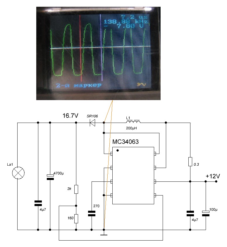
I have wired up the following circuit:
The image is reversed such that the pinout matches that of the actual chip.
And the component values in this circuit are not what I have actually used.
My own calulcations are as follows:
VOUT (V): 17.500000
IOUT (mA): 500.000000
VF DIODE (V): 0.750000
VSAT (V): 0.700000
FMIN (kHz) : 80.000000
VRIPPLE (V): 0.010000
tON / tOFF: 0.553097
(tON + tOFF): 0.000013
tOFF: 0.000008
tON: 0.000004
CT (pF): 178.062678
IPK (mA): 1553.097345
RSC (Ω): 1553.097345
CO(ųF): 2003.205128
LMIN(ųH): 32.388637
R1 (Ω): 1200
R2 (Ω): 15600
I have used a 100uH inductor, 0.22R for Rsc, 2200uF for Co and 201/200pF for Ct.
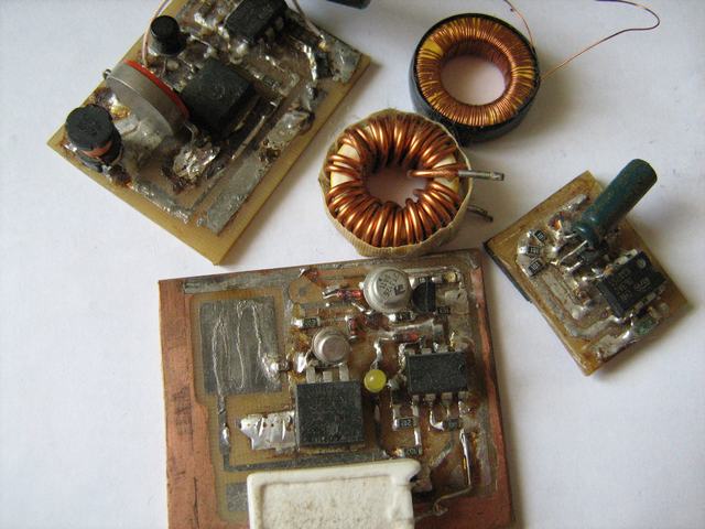
Here is the actual circuit - done with the short circuits one solderless kit:
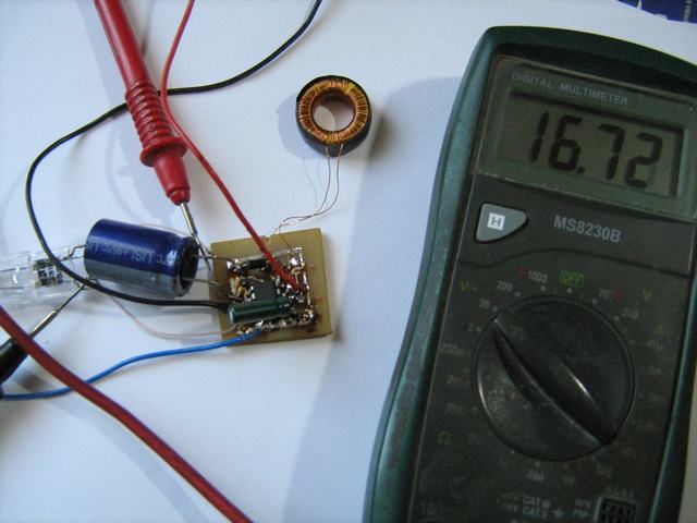
12V in and I get between 11V and 12V out. The calculations say it should be about 18V out.
12V input is on the right hand side.
Output is on the left hand side and I have added a 10k wire wound resistor as a load across it.
Why wont this f'ing thing work? I can't understand what I could be doing wrong as there is not that much to this circuit.
Strange thing is that I wired this up on my bread board and I did get it working with 18V out.
But I decided to wire it up using my son's Short Circuits kit because that corresponds directly to the prototype boards I am using. But apparently I have made exactly the same mistake with this as I did with the prototype board I soldered up. But I am damned if I can see what the mistake is.
Can anyone spot it or predict what it is likely to be?
The image is reversed such that the pinout matches that of the actual chip.
And the component values in this circuit are not what I have actually used.
My own calulcations are as follows:
VOUT (V): 17.500000
IOUT (mA): 500.000000
VF DIODE (V): 0.750000
VSAT (V): 0.700000
FMIN (kHz) : 80.000000
VRIPPLE (V): 0.010000
tON / tOFF: 0.553097
(tON + tOFF): 0.000013
tOFF: 0.000008
tON: 0.000004
CT (pF): 178.062678
IPK (mA): 1553.097345
RSC (Ω): 1553.097345
CO(ųF): 2003.205128
LMIN(ųH): 32.388637
R1 (Ω): 1200
R2 (Ω): 15600
I have used a 100uH inductor, 0.22R for Rsc, 2200uF for Co and 201/200pF for Ct.
Here is the actual circuit - done with the short circuits one solderless kit:
12V in and I get between 11V and 12V out. The calculations say it should be about 18V out.
12V input is on the right hand side.
Output is on the left hand side and I have added a 10k wire wound resistor as a load across it.
Why wont this f'ing thing work? I can't understand what I could be doing wrong as there is not that much to this circuit.
Strange thing is that I wired this up on my bread board and I did get it working with 18V out.
But I decided to wire it up using my son's Short Circuits kit because that corresponds directly to the prototype boards I am using. But apparently I have made exactly the same mistake with this as I did with the prototype board I soldered up. But I am damned if I can see what the mistake is.
Can anyone spot it or predict what it is likely to be?