Continue to Site

Welcome to EDAboard.com

Welcome to our site! EDAboard.com is an international Electronics Discussion Forum focused on EDA software, circuits, schematics, books, theory, papers, asic, pld, 8051, DSP, Network, RF, Analog Design, PCB, Service Manuals... and a whole lot more! To participate you need to register. Registration is free. Click here to register now.

Passive High Pass Filter Through a Differential Input

Status
Not open for further replies.

Iuri

Member level 2
Joined
May 14, 2011
Messages
50
Helped
3
Reputation
6
Reaction score
2
Trophy points
1,288
Activity points
1,630
I have a doubt about passive filters in differential inputs.
In low pass configuration I found this thread (https://www.edaboard.com/threads/176766/) that tells me to use the RC constant as:

R = R1 + R2
C = C1

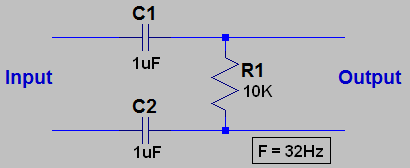
But, if I want a high pass do I need to use the same idea or something like this:

R = R1
C = C1 + C2

highpassfilter.png

Thanks!
 

Hi Iuri
Where is R2 in your picture ? it is a usual term to use C1=C2=C/2 in calculations .
Best Wishes
Goldsmith
 
  • Like
Reactions: Iuri

    Iuri

    Points: 2
    Helpful Answer Positive Rating
This picture attached is a high pass configuration, the R2 was referred for low pass one.

You answered my doubt, I should use C1=C2=C/2.

Thank you!
 

No. For the high pass circuit you should use C1=C2=C*2.
This will give F=1/(2*Pi*R*C).
 

For best sensitivity , low offset and best common mode noise rejection use an Instrumentation Amp IC ( 3 opamps) and use the series RC to define your HPF cutoff (fc=1/(2pi RC) instead of R7 You can get these in 1 chip too. R6=R5 and gain = R5/R7 for 1st stage... R2/R1 for 2nd stage
 

Hi Godfreyl
What you said ? are you sure about that ? if yes see below , please :
Consider that you have two capacitors in series together , the equal capacitor will be c/2 if both are correspond together . thus : if C1=C2=C/2 .
Respect
Goldsmith
 

Yes, you calculated the time constant for given C values, while godfreyl calculated capacitor values to achieve a given cut off frequency. Both calculations are correct.
 

So, should I use C1=C2=C*2 to achieve my cutoff frequency?
 

So, should I use C1=C2=C*2 to achieve my cutoff frequency?

Iuri, I don't know what you are going to connect at the diff. high pass output - however, realize that there is no ground connection (no bias current for a possible next stage).
 

LvW, I was thinking in a passive low pass as next stage and then connect to my differential ADC.
I didn't notice that. What do you suggest me?
 

The sample frequency will be 1000 samples/s. The low pass cutoff frequency is about 200hz.

I was concerned if 1st order is enough. Any suggestions?

Thank you!
 

It depends on the signal content above 500Hz . It will appear as noise with frequency transformed. (Alias)
Anything at 1KHz and all harmonics will appear as DC.
 

I know about Nyquist Theorem, but this is the first time I design something like that, so I don't have experience at all in anti-aliasing filter.

Should I use a higher order passive LPF or a active one?

Thank you.
 

Status
Not open for further replies.

Similar threads

Part and Inventory Search

Welcome to EDABoard.com

Sponsor

Back
Top