Continue to Site

Welcome to EDAboard.com

Welcome to our site! EDAboard.com is an international Electronics Discussion Forum focused on EDA software, circuits, schematics, books, theory, papers, asic, pld, 8051, DSP, Network, RF, Analog Design, PCB, Service Manuals... and a whole lot more! To participate you need to register. Registration is free. Click here to register now.

ADC Of LPC1768 cortex-m3 interface with CNY70

Status
Not open for further replies.

amirtafrishi

Junior Member level 1
Joined
Dec 16, 2011
Messages
19
Helped
0
Reputation
0
Reaction score
0
Trophy points
1,281
Activity points
1,449
Dear friends
I've got one LPC1768 & CNY70 sensor. Could anyone give me a sample example for controlling ADC for CNY70 please?
Also I’ve checked keili examples sample but they were so complicated, I didn’t get which Defines are needed for this simple program.
I would be thankful if you could help me :)
 

If you redan datasheet of CNY70 you can notice that output is more digital than analog. So you dont need ADC.
 
If you redan datasheet of CNY70 you can notice that output is more digital than analog. So you dont need ADC.

It depends on what you wan to do, if you just want to know if there is an object in front of the sensor then an digital input will be fine but if you care to read the proximity of the object then you need an analog input.

Alex
 
To be honest, i need it for line follower robot... for example voltage between 0 to 1.6 it activate port0.0 as high for upper than that make it low. I just want to have this sample for expanding my algorithm as line follower robot. Can u help me with that?
Also i've written a program which has problem that i dont know where
It's the sample that i've written:

Code:
#include "lpc17xx.h"
#include "type.h"
#include "adc.h"
{
LPC_GPIO2->FIODIR = 0x000000FF;
LPC_ADC->ADCR |= 1 << 24;
while((LPC_ADC->ADDR0 & (1 << 31)) == 0);
int curVal=( LPC_ADC->ADDR0 >> 4 ) & 0xFFF;
float volt = (float)(((VREFP-VREFN)*curVal)/ADC_MAX); //result in volts.
if ( volt >= 1.6 )
LPC_GPIO2->FIOSET = 1;
if ( volt =< 1.6)
LPC_GPIO2->FIOCLR = 0x000000FF;
return; /* the ADC reading is done inside the handler, return 0. */
}
It gives error like :adc.c(25): error: #169: expected a declaration

- - - Updated - - -

So as u said i need to be precise about input analog
 
Last edited by a moderator:

Guys could u please answer it as quickly as possible i need it urgently :)
 

To be honest, it gives errors on many parts for example it says that most of defines for example LPC_ADC->ADDR0 is undefined.Could u please give me a sample ? For example i looked to keil example which is really complicated & i didn't reach any conclusion then i search net and wrote down this program in same headerfiles of keil example but it gives error in most parts...

- - - Updated - - -

12.jpg22.jpg

Have look please :)
 

Thanks for yours greats attention. I used the quick example but again same errors apeared 12312.jpg
Am i missing any headerfile ?
 

something is wrong with your LPC17xx.h file.
Change #include "lpc17xx.h" with #include <lpc17xx.h> and try again
 
To be honest, i need it for line follower robot... for example voltage between 0 to 1.6 it activate port0.0 as high for upper than that make it low. I just want to have this sample for expanding my algorithm as line follower robot. Can u help me with that?
Also i've written a program which has problem that i dont know where
It's the sample that i've written:

So as u said i need to be precise about input analog

You can look at the attached code from Keil. It shows how to use the ADC on LPC1768.

Also for the CNY70, how do you connect it to the processor? Are you connecting one side of the transistor to the VCC and the other side to the ground via a resistor? Because that is the only way you can get a voltage output from CNY70.

Hope the source code helps.

Best regards,
Farhad
View attachment LPC1768_ADC.zip
 
initially,I am so thankful about your great attention.Yep,You are right, I've connect it exactly like that. actually my biggest problem relates to determining the structure of codes in Keil for example in below code i don't know which function defines ADC & which check them, Could you please guide me about that?
code:

Code C - [expand]
1
2
3
4
5
6
7
8
9
10
11
12
13
14
15
16
17
18
19
20
21
22
23
24
25
26
27
28
29
30
31
32
33
34
35
36
37
38
39
40
41
42
43
44
45
46
/*****************************************************************************
** Function name:       ADCRead
**
** Descriptions:        Read ADC channel
**
** parameters:          Channel number
** Returned value:      Value read, if interrupt driven, return channel #
** 
*****************************************************************************/
uint32_t ADCRead( uint8_t channelNum )
{
#if !ADC_INTERRUPT_FLAG
  uint32_t regVal, ADC_Data;
#endif
 
  /* channel number is 0 through 7 */
  if ( channelNum >= ADC_NUM )
  {
    channelNum = 0;     /* reset channel number to 0 */
  }
  LPC_ADC->CR &= 0xFFFFFF00;
  LPC_ADC->CR |= (1 << 24) | (1 << channelNum); 
                /* switch channel,start A/D convert */
#if !ADC_INTERRUPT_FLAG
  while ( 1 )           /* wait until end of A/D convert */
  {
    regVal = LPC_ADC->DR[channelNum];
    /* read result of A/D conversion */
    if ( regVal & ADC_DONE )
    {
      break;
    }
  } 
        
  LPC_ADC->CR &= 0xF8FFFFFF;    /* stop ADC now */    
  if ( regVal & ADC_OVERRUN )   /* save data when it's not overrun, otherwise, return zero */
  {
    return ( 0 );
  }
  ADC_Data = ( regVal >> 4 ) & 0xFFF;
  return ( ADC_Data );  /* return A/D conversion value */
#else
  return ( channelNum );    /* if it's interrupt driven, the ADC reading is 
                            done inside the handler. so, return channel number */
#endif
}


Am i paste write sample codes in ADC keil example & could u please tell the process of these functions?
Thanks
Yours faithfully

- - - Updated - - -

Furthermore, Am i concentrate to right part "ADCRead" ? Does ADCInit , ADC_IRQHandler,ADC0BurstRead play significant role in my simple program for CNY70 in ADC example(just for configuring the difference of voltages in ADC ports)?
 
Last edited by a moderator:

Furthermore, Am i concentrate to right part "ADCRead" ? Does ADCInit , ADC_IRQHandler,ADC0BurstRead play significant role in my simple program for CNY70 in ADC example(just for configuring the difference of voltages in ADC ports)?


Well, I think you need to read the datasheet of your processor before trying to figure out what this code does. The code is very simple, explained in details what it does and if you had any previous experience with microcontrollers, you should understand this.

For any micro controller, you need to do the following:
- Initialize the block, set up the IO ports to the right format/function, setup up the parameters for the controller, in this case ADC
- For ADC, you can read the data 'polling' or when interrupt happens. The ADC takes time to convert the analog data to digital, that is why you have to poll the control register to see when the conversion is done, or let the Interrupt controller to be called when ADC is ready to deliver the digital data

This has nothing to do with CNY70, it is a generic code for any analog input on that processor.

What I suggest you should do is to check Google for the question, there are 100s of links many of them with very good answers. Read them and see if you get your answer.
Also, one problem that many people have is they connect the voltages of the LPC1768 to the wrong source. Check those out and see if they are OK (I think Philips has an App-note for that).

Good luck with your project.
 
Thanks for your help dear farhada. I've tried to Learn the process of ADC programming & right now i've faced with confusing problem.I've written below program: i want in this program system firstly show a simple blink is beginning then go & check first ADC(0) of chip if it's high keep in loop but if not break the loop & start blinking but when put over 3.3+ voltage, It just jump to last blinking diode loop.could please look at my codes? is there problem in my codes or it related to electronic issue?code:


Code C - [expand]
1
2
3
4
5
6
7
8
9
10
11
12
13
14
15
16
17
18
19
20
21
22
23
24
25
26
27
28
29
30
31
32
33
34
35
36
37
38
39
40
41
42
43
44
45
46
47
48
49
50
#include "lpc17xx.h"
#include "type.h"
#include "adc.h"
extern volatile uint32_t ADCValue[ADC_NUM];
extern volatile uint32_t ADCIntDone;
extern volatile uint32_t OverRunCounter;
 
/*****************************************************************************
**   Main Function  main()
******************************************************************************/
int main (void)
{
 uint32_t i, j,L,volt;
  /* SystemClockUpdate() updates the SystemFrequency variable */
  SystemClockUpdate();
 
 LPC_GPIO2->FIODIR = 0x000000FF;        /* P2.xx defined as Outputs */
 LPC_GPIO2->FIOCLR = 0x000000FF;        /* turn off all the LEDs */
 
    for(i = 0; i < 8; i++)
    {
      LPC_GPIO2->FIOSET = 1 << i;
      for(j = 1000000; j > 0; j--);
    }
    LPC_GPIO2->FIOCLR = 0x000000FF;
    for(j = 1000000; j > 0; j--);  
  /* Initialize ADC  */
  ADCInit( ADC_CLK );
  while(1)
  {
L = ADCRead(0);
L = (L >> 4) & 0x00000FFF;
volt = (float)((3.3*L)/5);
if ( volt < 4 )     
break;
}
 
while(1){
 LPC_GPIO2->FIOCLR = 0x000000FF;        /* turn off all the LEDs */
 
    for(i = 0; i < 8; i++)
    {
      LPC_GPIO2->FIOSET = 1 << i;
      for(j = 1000000; j > 0; j--);
    }
    LPC_GPIO2->FIOCLR = 0x000000FF;
    for(j = 1000000; j > 0; j--);  }
 
 
   }


yours faithfully
 
Last edited by a moderator:

What is this line supposed to do :
Code:
volt = (float)((3.3*L)/5);

The ADC result voltage is (Vref * result)/ max_ADC_value so why do you divide by 5?

I would suggest you make your life easier and get rid of the float, use 3300 instead of 3.3 and you will get the result in milli volts without any need to use floats and a you'll get a high enough precision
 
Thanks for your great attention.exactly you are right, i will do that.Also, Do u see other problems in my code?please inform me.:)

- - - Updated - - -

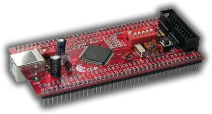
I did the what you said but again chip dosnt responde to my if function,I think maybe i have problem in VRefp & verfN.I dont have those sign on my board .Could please tell me what should i do? This is my board picture & circuit diagram:
6_1346597280.jpg
 

Attachments

  • Sheet1.pdf
    49.7 KB · Views: 147

There are no such pins in the chip, there is only a Vref that should be connected to 3.3v, have you done that or is it connected on the board?
Do you have a schematic of the board to check?
 

And my code is now like this :
Code:
L = ADCRead(0);
L = (L >> 4) & 0x00000FFF;
if ( volt < 1100 ) 	
break;
}
i put high in ADC(0) but It again jump to blinking loop after resting ....
 

Dear Alexan
Yep, It's Got vref Bottom. I plug it on. I thought maybe i miss any connection.you think why my code doesn't recognize the difference between voltages?am i making mistake in If function?
 

in post #18 the volt calculation is missing

- - - Updated - - -

use a voltmeter to check if vref is connected to 3.3 on the board, if not then use external voltage.
Normally it should be connected.
 
Status
Not open for further replies.

Similar threads

Part and Inventory Search

Welcome to EDABoard.com

Sponsor

Back
Top