Continue to Site

Welcome to EDAboard.com

Welcome to our site! EDAboard.com is an international Electronics Discussion Forum focused on EDA software, circuits, schematics, books, theory, papers, asic, pld, 8051, DSP, Network, RF, Analog Design, PCB, Service Manuals... and a whole lot more! To participate you need to register. Registration is free. Click here to register now.

Current to voltage converter

Status
Not open for further replies.

vishumittal

Newbie level 6
Joined
Aug 17, 2012
Messages
12
Helped
0
Reputation
0
Reaction score
0
Trophy points
1,281
Activity points
1,357
Sir, I want to convert the current (ranges 1uA - 1pA) into voltage (0-10V), Can you pls help me? the output voltage should have been a function of the input current and not a constant. Means that the voltage should change as the current changes
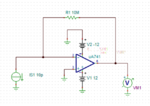
 

This does not work, the amount of current is very low and the output voltage should range in between 0-10V.
Please help.
 

**broken link removed**
 

This does not work, the amount of current is very low and the output voltage should range in between 0-10V.
If the feedback resistor is 10M, then you will get 0=>10V output with 0=>1uA input.
 

Can you please elaborate it?
I have the current from 1pA - 1mA and i want the output ranging between 0-10V and output voltage should not be constant, it should change when current changes.


but its not working, can you please help me in designing the circuit?

- - - Updated - - -

Sir, I cannot change the value of resistance every time, that is the point, I need a single circuit for the different inputs and outputs.
 

It is a single circuit. There is only one resistor. You never have to change it.

I don't know what resistor you need because first you said this:

current (ranges 1uA - 1pA)
and then you said this:
current from 1pA - 1mA

Which is it?

- - - Updated - - -

but its not working....
How do you know, did you try it? Can you show your circuit?

The opamp must have a dual power supply such as +12V and -12V.
 

Current range is 10pA -10mA.
I have attached the circuit also.
Please tell me if there is any mistake and help me.
Thank You. New Picture.png
 

Keep in mind that with most traditional amplifiers 10pA will be overwhelmed by non ideal parameters. The input bias currents may easily be in the order of tens of nanoamperes. ~80nA typical for the 741
 

741 is too cheap for this task ......
 

Use a really low input bias current amplifier.

This one may be an overkill and propably really expensive

https://www.ti.com/lit/ds/symlink/lmp7721.pdf

but you may find similar ones which feature low enough input bias currents for your 10pA lower limit.
 
Will this amplifier works?
Will the circuit remains same as shown above?

- - - Updated - - -

can you please help me by giving names of some other amplifiers which may work? Thank You.
This amplifier is not listed in the software I am using.
 

The amplifier in the datasheet works in the same manner as your circuit. Even the typical circuit diagram for the amplifier in the datasheet is the same. But typical however doesn't necessarily mean 'complete' and extra circuit components may be needed for signal conditioning for example.

Part of the design process is finding components. Search for "low input bias current amplifiers".

Your software may not have a amplifier with low enough input bias current. In which case you need to find a model for a amplifier that does and implement it in your software.
 
I am trying but there are not many amplifiers which have the input bias current of order of femtoampere.
Thanking You.
 

Current range is 10pA -10mA.
I have attached the circuit also.
The circuit is correct but for this current range the resistor should be 1K.

Then the circuit will behave like this:
10mA input gives 10V output.
5mA input gives 5V output.
2mA input gives 2V output.
1mA input gives 1V output.
0mA input gives 0V output.

As others have said there will be some inaccuracy with very small input currents. I don't think that is important. Why would you ever want to measure 10pA of current?

Even if you make a perfect circuit with a perfect opamp, 10pA input will give only 10nV output.

What do you want to use the circuit for?
Where does the current come from that you want to measure?
What will you do with the output voltage?
 
Last edited:

I have use the circuit for my project and I have the instrument which can measure the current in order of pA, I need the output as a voltage to make it work for the further process.
If you have some option, please help me.
Thank You.
 

I guess your scale is too big.... 10pA -10mA
strange project, my friend
 

Status
Not open for further replies.

Similar threads

Part and Inventory Search

Welcome to EDABoard.com

Sponsor

Back
Top